



2D Drawings
3D CAD
Generative AI
August 31, 2026
How Far Can AI Automate 2D-to-3D Drawing Conversion? Part Drawings, General Arrangements and Outsourcing
 Updated on 2026/08/31
Index
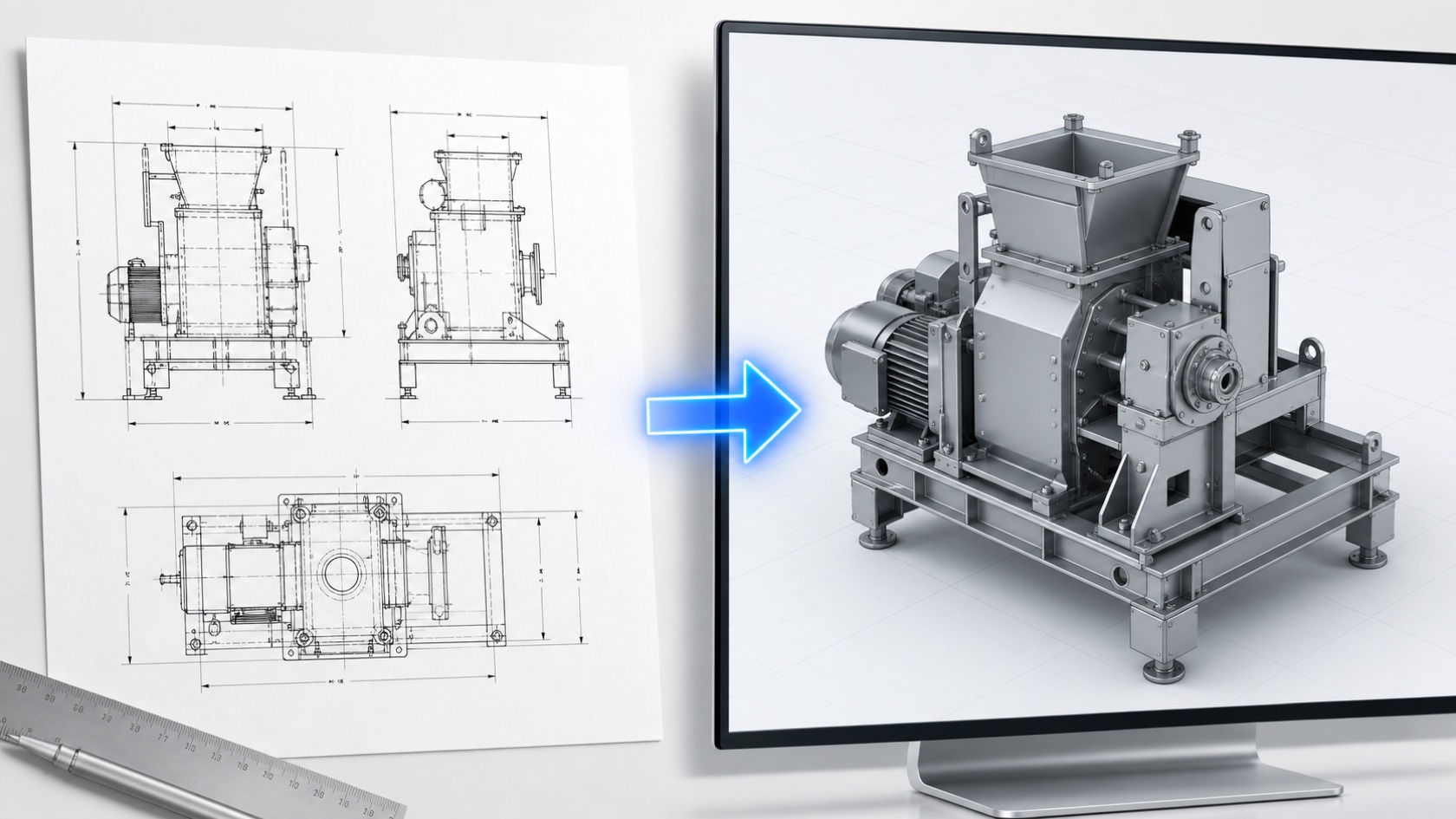
“How far can AI automate the conversion of 2D drawings into 3D?” The short answer: whether it can be automated is decided almost entirely by the product of two things — the type of drawing, and how strict a reconstruction you need.
Converting 2D drawings into 3D means building solid data that a 3D CAD system can handle, starting from drawings held on paper, in PDF, or in 2D CAD. As of 2026 this is not a yes-or-no question. Strictly reconstructing a part drawing and raising an outline from a general-arrangement or outline drawing are different problems, needing different technology and sitting at different levels of maturity.
What gets lumped together as “3D conversion with AI” also splits in two. Having a generative AI read the drawing and reconstructing the shape with an algorithm behave very differently. Compare them as one thing and your requirements will never settle.
This article first breaks down what “we want it in 3D” actually means by use case, separates the two AI approaches, and then sets out the capabilities and limits for part drawings and outline drawings in turn. It then covers the input-data conditions that decide success, outsourcing rates and where each option fits, and how far AI is likely to take this over time.
Key points
- Success is decided by two axes: part drawing or general-arrangement (outline) drawing, and outline reconstruction or strict reconstruction. The realistic targets are part drawing × strict and outline drawing × outline reconstruction; general arrangement × strict is the hardest case today
- “3D conversion with AI” covers two approaches. Letting a generative AI read the drawing handles a wider range of drawings but cannot tell when it has got the shape wrong; algorithmic reconstruction has stricter input conditions but produces stable results. In practice the direction of travel is AI for pre-processing, algorithms for shape reconstruction
- 3D conversion from outline drawings is beginning to reach practical use. This is not a matter of “roughly right” — the question is whether the outline can be strictly reconstructed from the orthographic views
- Part drawings carry the information. They are drawn so the part can be made, so hidden lines and dimensions are relatively complete. The barriers are free-form and irregular shapes, the fact that the generated 3D cannot be edited in CAD (no features come back), and shape misreads that go unnoticed
- By hand, a single unit takes about 8 hours. Stacked up into a full equipment set that becomes around 200 hours, roughly two weeks. What matters is lead-time reduction more than hour reduction
- Input data decides about 90% of it: DXF/DWG, third-angle projection, views from several directions, and dimension lines and hidden lines sorted out. PDF and paper lose the line information through rasterisation
- Outsourcing and AI are not mutually exclusive. Published rates start around 3,800 yen per hour for part modelling and 5,500 yen per hour for assembly drawings — the general-arrangement side costs more. Difficulty and price point the same way. The practical answer is automatic generation plus human finishing
The three things people really want to know
Searches on this topic break down into three questions.
- Can our drawings be converted to 3D automatically? (feasibility)
- If not, what does outsourcing cost and how long does it take? (the alternative)
- How much better will AI get? (when to invest)
Before any of these, though, one thing has to be settled: what the 3D is for. Without that, the same question — “can you convert this?” — gets opposite answers.
| Purpose of the 3D | Fidelity required | How realistic automation is |
|---|---|---|
| Process and plant layout studies, clash checks, delivery route planning | The outline needs to be legible | ○ Beginning to reach practical use |
| Explaining to the shop floor and other departments, checking workability in VR | It needs to be understandable at a glance | ○ Beginning to reach practical use |
| Placing equipment in BIM, customer-facing proposals | Outline plus roughly the right appearance | ○ Combine generation with 3D catalogue data |
| Input to CAM and machining programs | Dimensions must match the drawing | △ Automatic generation with human checking assumed |
| A base for design reuse and design changes | Dimensional match plus editability in CAD (changing hole diameters and pitches later) | ✕〜△ Human work is still required |
The gap shows up plainly in customer conversations. For machining programs, “the model dimensions go straight into the program, so a large discrepancy against the drawing changes the part that comes out.” For an equipment layout study, being able to read the outline is enough. The same words, entirely different requirements.
So the first step is to reframe the question: not “can you convert this to 3D?” but “can you produce 3D good enough for this use?”
“3D conversion with AI” means two different things
There is a second distinction to draw before comparing anything. Even within “converting 2D drawings to 3D with AI”, there are two different mechanisms.
| Approach | What it does | Strength | Weakness |
|---|---|---|---|
| Generative AI reads the drawing | The drawing is fed to a model as an image or line data and the shape is inferred | Handles a wide range of drawings, including incomplete or hand-drawn ones | A misread still produces a plausible solid. The error is hard to notice |
| Algorithmic reconstruction | Lines are interpreted as geometry and a solid is assembled so that the views agree | Stable results when conditions are met; what cannot be reconstructed is explicit | Strict input conditions. Nothing is generated if the drawing is not clean |
In practice this is not either/or. The direction is AI for pre-processing (line-type classification, drawing recognition) and algorithms for shape reconstruction. Where this article says “automation”, it means that combination.
Part drawings and general-arrangement (outline) drawings are different problems
They are described with one phrase, but the structure of the difficulty is completely different. Skip this split and the requirements never settle.
Put drawing type on one axis and required strictness on the other, and four quadrants appear.
| Outline reconstruction (the shape is legible) | Strict reconstruction (dimensions and shape match the drawing) | |
|---|---|---|
| Part drawing | Almost anyone can do this. A general-purpose generative AI produces something plausible. Little reason for a dedicated tool | Realistically achievable. The drawing carries the information needed to make the part, so it can be reconstructed when conditions are met |
| General arrangement / outline drawing | Beginning to reach practical use. Matches the layout-study use case | The hardest case today. The information is simply not in the drawing |
The two quadrants worth investing in are part drawing × strict and outline drawing × outline reconstruction. The top-left needs no dedicated solution. The bottom-right is a two-stage problem: strict reconstruction of part drawings has to work first, and then a separate algorithm has to assemble them.
A common misreading: “outline reconstruction” does not mean “rough is fine”
Read “outline reconstruction” as “a bit off is acceptable” and the evaluation goes wrong.
The question here is not dimensional deviation. It is whether the outline can be strictly reconstructed from the orthographic views. Some shapes are not uniquely determined by the views alone; overlapping lines cause shapes to be misinterpreted. This is a question of reconstructed or not, not of how many millimetres out it is.
So evaluate results the same way: not “what is the tolerance in millimetres?” but “does it match the original outline, and where does it not?”
Why part drawings can be reconstructed strictly
Because a part drawing is drawn so that the part can be made.
The machinist has to be able to determine the shape, so hidden lines are normally drawn. When something is missing, the machine shop or the supplier asks, and it gets corrected in the course of the work. As a result, part drawings are likely to be complete — a decisive advantage for automation.
How much information does a general-arrangement drawing carry?
It depends entirely on what the drawing was made for. “General arrangement drawings carry less information” is not a rule.
That said, the need that reaches us is largely this: the receiving company has to be able to read the outline of a unit or machine from a drawing it was given. Place someone else’s equipment into your own layout and check for clashes, route the piping, plan the delivery path. That calls for the outline, not the internal structure.
Drawings made for that purpose normally leave out the internal detail. And drawings received from suppliers sometimes have information removed deliberately, to avoid disclosing technical know-how. Missing dimensions, absent hidden lines, simplified geometry — that is the operating practice, not a defect in the drawing.
Which is exactly why strict reconstruction from a general-arrangement drawing runs into a wall: the information is not in the source data.
Part drawings: what works, and where it breaks
What works
- Parts that can be expressed as combinations of straight lines, arcs and tapers can realistically be reconstructed when the orthographic views are complete
- Sheet-metal parts are among the easier cases to raise from views taken in several directions
- Generation itself is fast — results come back in tens of seconds to a few minutes
Four barriers
1. Weak on irregular and free-form shapes
Current-generation automatic generation mostly approximates shapes with combinations of basic solids. Parts with angled cuts or three-dimensional curved surfaces are not reproduced as they are.
In our own verification against equipment part drawings, none of the part drawings could be generated automatically: the irregular shapes did not fit within the approximation. Limit the scope to what a machine tool can produce — straight lines, arcs and tapers — and it becomes a workable target. Some projects proceed with the requirement explicitly narrowed: “three-dimensional curved surfaces are out of scope.”
2. Features do not come back
This is the biggest practical barrier.
Export the 3D through an intermediate format such as STEP and you get the resulting shape only — the construction history (extrudes, holes) is not included. What design teams actually want to do next is change a hole diameter or a hole pitch. Without that, the model cannot serve as a base for design reuse.
In other words, “converting to 3D” and “making it editable in your CAD” are two separate problems. Write the requirement without separating them and the result will not be what was expected.
3. The required precision differs by orders of magnitude
When the model feeds a machining program, its dimensions become the part’s dimensions. “Roughly right” is unusable here. In fact, not generating the parts you are unsure about produces less rework than generating them.
4. The real danger is a shape misread — and it cannot be self-detected
Having a generative AI read a drawing carries two kinds of risk.
- Missed dimensions: a proportion of the dimensions on the drawing is not picked up
- Shape misreads: the lines are interpreted incorrectly and a model of a different shape is produced
The second is the serious one. Dimensions may be missed, but the values that are read are rarely wrong. Shape interpretation is different: when the shape comes out wrong, the system itself cannot tell. A plausible solid appears, and the error surfaces only when a person compares it against the original drawing.
For this reason, guaranteeing the correctness of the output automatically, from the 2D drawing alone, is not realistic today. A verification step has to be built into the process.
General-arrangement and outline drawings: what works, and where it breaks
What works
Raising an outline in 3D from a general-arrangement or outline drawing is beginning to reach practical use, because it matches the layout-study use case.
WOGO is working with Sanki Engineering on the joint development of TRANDIM, software that generates 3D models automatically from 2D drawings. It takes DXF and DWG drawings and generates 3D models of equipment. Sanki Engineering’s announcement states that model creation, which has taken roughly 2 to 7 hours per unit, is expected to be reduced by up to 90%. Output supports IFC and other formats, and productisation and sale are planned within fiscal 2026.
The use cases go beyond building services.
- Factory and process layout studies in manufacturing (arranging equipment, checking clashes and circulation)
- Piping design, feasibility checks for installation work, delivery route planning
- Checking workability in VR (operator movement, tool access during maintenance)
- Placing equipment in BIM
- Customer-facing proposals
What these share is that the 3D is not being drawn in order to make something — it is being drawn to study something before it is made. On sites moving to 3D for equipment, few people can read a 2D drawing fluently, so converting to 3D so that operators and other departments can see it is itself a significant need. Here, a legible outline does the job.
How many hours does this take today?
To judge the investment, you need the hours you are replacing.
| Unit | Hours by hand |
|---|---|
| One unit (a pump, a heat-source unit and so on) | About 8 hours — a figure we have confirmed through our own verification and support work. Published figures put it at roughly 2 to 7 hours per unit |
| One full equipment set (a production line or facility made up of many units) | Around 200 hours, roughly two weeks |
The point is that sites are not dealing with one unit at a time. A few hours per unit becomes around 200 hours once it stacks up into a full equipment set.
This work also arrives in bursts rather than continuously. Equipment replacement is concentrated in the long holidays when the line is stopped, and the source drawings only arrive from the supplier, so the work is hard to bring forward. The result is a hard constraint: one equipment set per long holiday is the limit.
What matters here is lead time more than raw hours. The same 200 hours taken over two weeks or over a few days is the difference between fitting into the construction plan and not. That is usually where the motivation to automate comes from.
Three barriers
1. Can the outline be reconstructed strictly?
In our verification, every general-arrangement drawing was generated in 3D, but differences against the original shape remained, caused by misrecognition where lines overlapped. The assessment on site was that it “can be used for layout studies, but not directly as equipment data.” That distance is close to the reality in 2026.
To repeat: this is not “it was off by so many millimetres” but shapes coming out different from the original in places. Reproducing polygons and radii sits one step above where the current generation is.
2. The input drawing does not carry enough information
As above, outline drawings omit internal detail and may carry no dimensions or hidden lines. Older drawings frequently lack a complete set of views. No technology can reconstruct information that is not in the input.
3. Handling bought-in units
General-arrangement drawings include bought-in items such as cylinders, pumps and valves. Where the manufacturer publishes 3D data, downloading and placing it is more reliable than generating it. However, the number of products with a published 3D catalogue is still limited. Checking early whether 3D catalogue data is available for the units in question makes the scope of what actually needs generating much clearer.
Input data decides most of it
In practice, the judgement comes down almost entirely to the condition of the input data. When a feasibility view can be given at the first conversation, it is usually because this has been checked.
| Check | Good | Difficult |
|---|---|---|
| Data format | DXF or DWG, where lines are structured as lines | Rasterised PDF, paper, hand-drawn. A pixel array loses the fact that a circle is a circle |
| Projection and views | Third-angle projection with views from several directions | Front view only, or front and right side only. Older drawings are less complete |
| Line handling | Dimension lines, notes and balloons removed; hidden lines identified | Dimension lines and balloons mixed in. Treating solid and dashed lines alike causes misrecognition |
| Agreement between views | Shapes agree from view to view | Top and front views disagree. Even a small discrepancy can break generation |
| Drawing conventions | Drawn to a general standard such as JIS | In-house symbols — “a double-dot chain line means a duct”. People read them; machines do not |
Vector PDFs are handled by some services, but rasterised PDFs and paper drawings need a separate line-extraction step first.
That last row is easy to overlook, but this is where the rule-definition cost sits. When drawing conventions run to hundreds or thousands of variations, defining all of them as rules can cost more than the hours automation saves. Scope automation by drawing pattern.
Outsourcing: rates and where it fits
Where automation does not hold, outsourcing is the realistic option. The CAD outsourcing market is mature and rates are published.
Published rates (as of August 2026)
| Work | Guide price |
|---|---|
| Drawing tracing (A3) | 5,000–10,000 yen per sheet |
| New part drawing | From around 5,000 yen per sheet |
| Assembly drawing (A1) | Around 40,000 yen |
| Hourly rate (2D CAD) | Around 3,000 yen |
| Hourly rate (3D CAD) | Around 3,500 yen |
| Modelling (parts) | From 3,800 yen per hour |
| Drawing breakdown (part drawings) | From 4,200 yen per hour |
| Drawing breakdown (assembly) / 3D assembly | From 5,500 yen per hour |
| 3D model creation | From 50,000 yen per model (technical rate up to 6,500 yen per hour) |
| Typical lead time | 7 days to about 3 weeks |
Note that assembly work is priced higher than part work. It is harder by hand too. Difficulty and price point the same way as automation difficulty does.
Offshore outsourcing to Vietnam and elsewhere brings the unit price down. In building services and construction, sending 2D design drawings to an overseas group company or partner for modelling is already an established workflow at some firms. Evaluate not only the unit price but the incoming inspection and coordination hours that come with running it that way.
Where outsourcing fits, and where automation fits
| Outsourcing fits | Automation fits | |
|---|---|---|
| Drawing condition | Incomplete, simplified, mixed with paper and hand-drawn sheets | DXF available, views complete |
| Geometry | Includes free-form and irregular shapes | Straight lines, arcs, tapers |
| Interpretation needed | Design intent has to be inferred from what is not on the drawing | Reproducing what is drawn is enough |
| Volume and frequency | One-off, a few times a year | The same kind of drawing recurs |
| Main goal | Reducing hours | Reducing lead time |
That last row matters. Outsourcing moves the hours outside, but it does not shorten lead time, because the round trip — request, estimate, work, incoming inspection, integration — remains. As set out above, a full equipment set takes around 200 hours over roughly two weeks, with a hard deadline attached. In that kind of work, lead time bites harder than hours. Send the hours out and the round trip still stands — which is where the motivation to automate comes from.
Decide these before you place an order
- What data you can supply (is there an original DXF? Often it sits with the design department or a partner firm)
- Delivery CAD format (STEP / Parasolid / IFC / native)
- Whether features are required (essential if you intend to edit later)
- What counts as a pass (the incoming inspection standard. Leave it unwritten and it will be disputed)
- Tolerances, materials and part function (they change the basis of the estimate)
- NDA
Choose on price alone and the checking step may have been left out. Compare on the basis that includes your own incoming inspection hours.
How far will AI take this?
This is the part that bears directly on timing, so here is where things stand and where they are going.
Where we are: three routes and their limits
There are three broad routes to generating 3D automatically: from text, from a 3D scan (point cloud), and from 2D drawings. None of them is at 100% today; approximation or inference enters somewhere. That is the premise to start from.
| Area | Where it stands in 2026 |
|---|---|
| Outline generation from outline drawings | Beginning to reach practical use. Usable for layout and clash studies. Exact shape agreement is the open problem |
| Strict reconstruction from part drawings | Achievable if the geometry is narrowed. Starting from a PoC is realistic |
| Strict reconstruction from general-arrangement drawings | Not there. Needs strict part reconstruction plus assembly, in two stages |
| Hand-drawn and paper drawings | A separate line-extraction step is needed first, and precision is limited |
Near term (within a year): pre-processing and wider inputs
1. Automatic line-type classification
If lines can be classified automatically as solid, hidden, dimension or note, the manual pre-processing — deleting dimension lines and hidden lines before handing the file over — disappears. We are working on this classification, and it will widen the range of drawings that can be handled considerably. Pre-processing is unglamorous, but increasing the number of drawings you can address often matters more than raising precision.
2. Wider input formats
DXF and DWG are the current ground. Vector PDF support already exists. Raster images and paper come next, tied directly to progress in drawing OCR.
3. Delivery as a service becomes normal
Web services that return 3D data within minutes to one business day from uploaded orthographic views started appearing in 2025. Being able to try it without deploying a tool has lowered the barrier to evaluation considerably. Throwing a few of your own drawings at it and seeing how much comes back is now a practical first step.
Medium term (one to three years): precision and usability
4. General-purpose models plus domain constraints
This is where we expect the largest effect. General-purpose drawing recognition on its own plateaus. Build in constraints specific to the industry and the product, however, and precision moves towards a usable level. Premises such as “this is formed from folded steel plate”, “the structure is double-walled”, “standard stock is the base” are enough to eliminate impossible shape candidates.
Put the other way round: narrowing to your own product domain and tuning is faster than waiting for a general-purpose solution that works on every drawing. We expect that structure to hold for some time.
5. Output in formats CAD can use
Generative AI is good at producing a plausible-looking mesh, but getting to a data format manufacturing can use is hard. Output as a B-rep solid rather than a mesh, and then feature assignment on top, is what makes it usable in design. Services that output B-rep solids in STEP are starting to appear, so this direction is comparatively easy to read.
6. Closing the loop between generation and verification
Against the “cannot self-detect a shape misread” problem above, an approach is emerging that regenerates drawings from the produced 3D, compares them against the original 2D, and reworks where they disagree, with a cap on iterations to force convergence.
7. Combining with point-cloud data
2D drawings alone are not enough information, and point clouds alone are not either. The two are complementary. Even for equipment with no drawings to hand, combining a scanned point cloud may yield 3D good enough for study work. The need is large, but the data are so different in nature that conversion costs are correspondingly high.
Longer term: removing the need to reconstruct at all
The more fundamental change is exchanging design information without going through a 2D drawing. If PMI (Product Manufacturing Information), which carries dimensions, tolerances and notes in the 3D data, and data structures that attach meaning to geometry become widespread, converting back from 2D stops being necessary.
That involves your suppliers and customers, not just your own organisation. As long as suppliers send 2D drawings, the need to reconstruct will remain. As a near-term improvement, investing in points 1 to 7 is more realistic.
What will not change
Information that is not on the drawing cannot be recovered, by AI or anything else.
- Strictly raising the original geometry from a general-arrangement drawing with the internals omitted
- Correctly interpreting tacit in-house conventions on first sight
- Learning design standards — why a dimension was chosen — from past drawings
The third matters most. Design standards are recorded neither in the drawings nor in the CAD data. Training on past data will not surface them. This is not a matter of waiting for technology; it is a question of how a company designs the way it draws and the way it holds data.
In summary
The highest return today comes from building “generate the outline automatically, finish the parts that need it by hand” into the work now, rather than waiting for full automation. Raising the efficiency of the manual editing alone shortens lead time significantly. On top of that, line-type classification, domain constraints, and closing the generation-verification loop will push scope and precision up in stages. That is our picture of the next three years.
How to decide for your own site
Three questions, in order.
Question 1: what is it for?
For layout studies and explanation, a legible outline is enough. Automation is realistic.
For CAM or design reuse, you need dimensional agreement and features. Design the process assuming human steps.
Question 2: part drawings or general-arrangement drawings?
Part drawings: worth evaluating if the geometry is mainly straight lines, arcs and tapers. Outsource if free-form surfaces dominate.
General arrangement and outline drawings: outline generation is beginning to reach practical use. In evaluation, look for where the result does not match the original outline.
Question 3: volume and lead time?
One-off or low volume — outsourcing is faster.
The same kind of drawing recurring, with lead time as the constraint — automation pays back.
Answer these three and you land naturally on automate, outsource, or both. For most companies the answer is the third: generate the outline automatically and finish the parts that need precision by hand.
WOGO’s 2D-to-3D generation and 3D design verification cover generating 3D models from 2D drawings and checking that what was generated matches the drawing. We take enquiries via our contact form, including confirming how much of your own sample drawings can be reconstructed.
Frequently asked questions about 2D-to-3D conversion
Can paper drawings or PDFs be converted to 3D?
Vector PDFs can be handled in some cases; rasterised PDFs and paper drawings cannot be used as they are. Raster formats hold the information as pixels, so structural information such as “this line is a circle” has been lost. A separate conversion into line data (DXF and so on) is needed first. Original DXF files often remain with the design department or a partner firm, so it is worth checking before you start.
Can old drawings without a complete set of views be converted?
It depends on the shape. Where front and side views determine the shape uniquely — a cylinder with a hole, for instance — it may be possible. Where there is only a front view, or where something is drawn in the front view but not in the side view, the missing information cannot be supplied by the system. Older drawings tend to assume tacit knowledge that only people familiar with that company’s drawings can read, and automating that is difficult today.
Can the generated 3D model be edited in our existing CAD?
It can be read in as geometry, but the construction cannot be edited as it stands. Handing over through an intermediate format such as STEP does not include feature information such as extrudes and holes. If you intend to change hole diameters or pitches later, confirm feature assignment as a requirement from the outset. “Can it be converted to 3D” and “can it be edited in CAD” are separate questions.
How do we confirm that an automatically generated 3D model is correct?
Build a step where a person compares it against the original 2D drawing. The thing to watch in automatic generation is not missed dimensions but shape misreads. When the shape comes out wrong, the system itself cannot tell. A plausible solid is produced, so appearance alone is not a reliable judgement. Running it alongside a verification mechanism — regenerating drawings from the produced 3D and comparing them with the original — is the reliable approach.
What does it cost to outsource 2D-to-3D conversion?
Published rates run around 3,000 to 6,500 yen per hour, or roughly 30,000 to 50,000 yen per 3D model. Assembly work is priced higher than part work, from around 5,500 yen per hour. Lead times run from 7 days to about 3 weeks. Offshore outsourcing lowers the unit price, but compare on a basis that includes your own incoming inspection and coordination hours.
Should we start with part drawings or general-arrangement drawings?
It depends on the goal: start with general-arrangement and outline drawings for layout studies, and with part drawings for machining or design reuse. 3D generation from outline drawings is already beginning to reach practical use, so results can be confirmed quickly. Strict reconstruction from part drawings is best started as a PoC on real data, with the target geometry narrowed. In either case, check first whether your drawings are in DXF and whether views from several directions are present. That gives you most of the feasibility picture.
Summary
How far AI can automate 2D-to-3D conversion is decided almost entirely by part drawing or general-arrangement (outline) drawing, times outline reconstruction or strict reconstruction. 3D generation from outline drawings is beginning to reach practical use, and strict reconstruction from part drawings is achievable if the geometry is narrowed. Strict reconstruction from general-arrangement drawings faces a structural constraint: the information is not in the drawing.
Outline reconstruction does not mean “a bit off is fine”. The question is whether the outline can be strictly reconstructed from the orthographic views, and evaluation should look for where the result does not match.
The biggest factor in feasibility is not technology but the condition of the input data. Is there a DXF? Are the views complete? Are the lines sorted out? Checking that alone narrows the direction considerably.
Automation and outsourcing are not opposites. Generate the outline automatically and finish the parts that need precision by hand — that combination gives the best return today.
WOGO works on automatic 3D generation from 2D drawings and on 3D design verification and automated drafting for what is generated. We can verify how much of your own sample drawings can be reproduced with current technology before answering. Tell us the drawings and the use case.
A reliable way to start: pick a few target drawings, check whether a DXF exists and whether views from several directions are present, then try it on real data. If you are interested in automatic 3D generation from 2D drawings, or in verifying what is generated, please get in touch via our materials request or contact form.
This article was written by WOGO Inc., a University of Tokyo-originated startup developing systems for 2D-to-3D conversion, design verification and automated drawing inspection in manufacturing using 3D, CAD and AI technologies.