



2D Drawings
3D CAD
Generative AI
August 12, 2026
How to Create Drawings Automatically with AI: Producing 2D Drawings from 3D Models and Cutting Drafting Hours
 Updated on 2026/08/12
Index
We are asked more and more often whether drawings can be created automatically with AI. The problem is that very different things are described with the same words.
The automated drawing creation covered in this article means using AI and algorithms to automate drafting work — placing views, breaking an assembly down into part drawings, and adding dimensions — based on design information such as a 3D model or existing drawings.
What matters is that this is not an AI that draws a complete drawing from a blank sheet. It is closer to reality to describe it as automation for designers who design in 3D CAD but still have to produce the 2D drawings the shop floor needs, and who are buried in that release work.
This article first separates the three types that are easily confused, then covers the automation that is closest to practical use in mechanical design — creating 2D drawings from a 3D model: what can be automated, what a person inputs, how it works, how it differs from earlier approaches, what to check when comparing products, and how to introduce it.
Key points of this article
- “Creating drawings with AI” splits into three types: (1) generating from conditions (architecture and layout), (2) reading drawings (OCR and drawing recognition), and (3) drafting from a 3D model (mechanical design). If they stay mixed together, requirements never settle
- In type (3), what automates well is view placement, drawing breakdown, filling in notes and parts lists, and dimensioning. What people handle is inputting design intent — datums, tolerances and grouping — plus the final check
- Because the drafting is done mechanically, missing dimensions and the rework they cause are reduced. This is where much of the time saving comes from
- Two things decide the outcome: fully automatic or partly automatic, and how much customisation your own drawing rules require (is drafting to general JIS practice enough, or must it match your company’s own rules?)
- Introduction proceeds step by step, by part type, not across all drawings at once. Start by checking how far the parts you need — from sheet metal and machined parts to more complex plastic parts — are already supported
What does it mean to create drawings automatically with AI? Start by separating the three types
Search results for “AI drawing creation” mix three types whose purpose and input data are completely different. Unless you decide which one matches your problem, product comparisons will talk past each other.
| Type | Input → output | Main uses and industries | Practicality in mechanical design |
|---|---|---|---|
| (1) Generating from conditions or text | Requirements, site conditions, regulations → floor plans, layout proposals | Architecture, housing, offices; in manufacturing, targets with standardised conditions such as jigs | Medium to low (possible for simple repeated shapes; hard to cover a wide variety of products) |
| (2) Reading drawings (OCR, drawing recognition) | Paper, PDF or TIFF drawings → dimension values, parts lists, quantities | Cost estimation, digitising drawings, searching past drawings | Medium (effective for reusing existing drawings) |
| (3) Drafting from a 3D model | 3D model, attributes, BOM → 2D drawing | Mechanical design and part manufacturing | High (the subject of this article) |
Type (1) automates “proposing something whose shape is not yet decided”. It became practical first in architectural layout, where constraints can be written as rules, and in manufacturing for simple repeated shapes. Rather than “it cannot produce part drawings”, the accurate reading is that it can generate standardised shapes from condition input.
Type (2) automates “extracting information from drawings that already exist”. It is the entry point to treating drawings as data, and it fits cost estimation and searching past drawings.
Type (3) automates “the shape is already decided; convert it into the drawing representation“. Because the 3D model is the correct answer, no creative proposal is needed; instead what is required is expressing it accurately according to in-house drafting rules. From here on, “automated drawing creation (automated drafting)” refers to this type (3).
Why 2D drawings are still needed even though 3D design is standard
Mechanical design in 3D CAD is now standard. Even so, the need to produce the 2D drawings used on the shop floor has not changed.
In recent years, PMI (Product Manufacturing Information) — holding dimensions, tolerances and notes inside the 3D data — has come into use. At present, however, it has not become a replacement for 2D drawings on the shop floor.
As a result, time goes not into design itself but into turning a decided shape into a drawing. At the sites we support, there are cases where 30–50% of a designer’s hours go into drafting-related work.
External research points the same way. Engineers report spending about a third of their time on non-value-added work, with 20% of their time spent working with outdated information (Tech-Clarity, "Reducing Non-Value Added Work in Engineering", 2014, 248 manufacturers). For 2D drawing creation itself, one part is said to take at least 30 minutes, with checking adding further time on top (MISUMI meviy). That is what gets automated.
WOGO covers type (3), the automation of drawing creation (automated drafting). By having the designer input datums, tolerance information and grouping against the 3D model, drafting that follows the design intent becomes possible. The main scope is sheet metal, machined and fabricated (plate-welded) parts, and we are progressively extending coverage to plastic parts and others.
When you create drawings from a 3D model, what is automated and what does a person input?
In short, the steps that can be written in shapes and numbers are automated, while design intent remains with people in the form of input given up front. Viewed as a single task, drafting looks like a choice between fully automatic and manual; broken into steps, the boundary is clear.
| Drafting step | Can it be automated? | What people handle / notes |
|---|---|---|
| Placing views, sections and detail views | Yes, automates well | How standard views are chosen can be made a rule. Which section best shows the key point involves intent |
| Drawing breakdown (assembly → part drawings) | Yes, automates well | Can be expanded mechanically from the structure and BOM. Ordering units and purchased parts depend on in-house rules |
| Notes, title block, parts list | Yes, automates well | Can be filled from 3D model attributes. Nothing is filled if the model has no attributes |
| Dimensioning | Varies widely by service | Partly automatic is common. We aim for fully automatic dimensioning; in exchange, information such as datums is input beforehand |
| Tolerances and geometric tolerances | Can be entered automatically once specified | Deciding where each tolerance belongs is done by people |
| Instructions that depend on the manufacturing method | People decide | Changes with the fabricator’s equipment and process. The same applies to welding instructions and surface treatment |
The step we are asked about most is dimensioning, and approaches differ by service. Some enter only the main dimensions automatically and leave the rest to a person; others enter every dimension automatically. The former requires people to check how much has been filled in; in the latter, the up-front input takes that place.
The way dimensions are handled is also not limited to “a person fixes the parts of the automatically generated dimensions that involve intent”. If you change the order so that a person inputs the intent first and dimensions follow from it, the amount of rework itself falls. On top of that:
- a person makes fine adjustments to the automatically generated dimensions
- the adjusted drawing is then checked by the machine to judge whether any dimensions are missing
This hybrid operation is possible too — combining human judgement and machine completeness by separating the steps.
How far does this actually work today?
We work on automation across design tasks in manufacturing: automated design, automated drawing release and automated design verification. For automated drafting, we have a public case — an 80% reduction from jig design to ordering drawings with Takahashi Metal Industries — that covers automated design through automated drawing release. At present we are rolling out general-purpose automated drawing release for sheet metal and machined parts, provided individually to several companies.
How a 2D drawing is produced from a 3D model
The flow is easiest to grasp in three stages: input, processing and output.
- Provide the required information: the 3D model can be linked from CAD through an API. In addition, the designer inputs datums, tolerance information and how parts are grouped. Company-specific constraints can be customised in advance
- Build the skeleton of the drawing: break the assembly down, choose and place standard views, and apply the sheet frame and title block
- Generate dimensions and notes: derive dimensions from the geometry, and fill notes and the parts list from attributes
- Check: either a person reviews the parts tied to design intent, or the machine checks for missing dimensions (the hybrid operation above)
- Release: output as a native CAD drawing, DXF or PDF
The conventional process, and the process with automated drafting
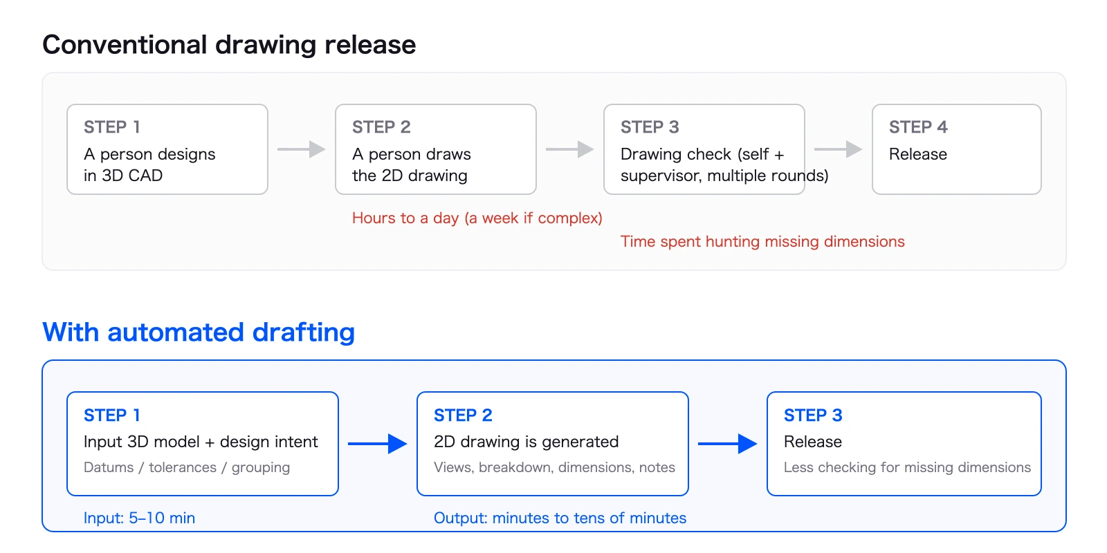
| Conventional | With automated drafting | |
|---|---|---|
| Process | (1) a person designs in 3D CAD → (2) a person draws the 2D drawing → (3) checking (by the designer, then a supervisor, in several rounds) → (4) done | (1) input the 3D model and the required information (datums, tolerances, grouping) → (2) the 2D drawing is output automatically |
| Time to draw the 2D drawing | A few hours at best, one to two days often; a complex drawing can take about a week | 5–10 minutes to input information; minutes to tens of minutes to output |
| Checking | A step is needed to hunt for missing dimensions and entry mistakes | Because dimensions are not structurally left out, less weight falls on checking for omissions |
There are three points worth drawing out.
First, what is reduced is not only “drawing time”. Conventionally, on top of the time to draw, there was the time to check for missing dimensions and entry mistakes, the time to fix what was found, and the rework when something was missed. Drafting mechanically reduces this “omission-derived” workload as a whole.
Second, human work does not go to zero. People input the datums, tolerances and grouping. That input is short compared with drawing a whole sheet, and it is the act of deciding design intent — which is the designer’s job.
Third, the quality of the input decides the quality of the output. Companies that have their own CAD conventions or drafting standards will need a corresponding amount of company-specific customisation of the automated drafting itself. How much a system depends on the way models are built differs by provider, so it belongs on your comparison checklist.
How this differs from earlier automation (macros, APIs and templates)
Automating drafting is not new. Many design departments have automated parts of it with the following means.
- Macros and APIs: recording or scripting CAD operations so that a fixed procedure runs repeatedly
- Templates and drawing reuse: copying the drawing of a similar part and rewriting dimensions and part numbers
- Parametric design: building parameters and relations into the model so that changing a dimension propagates through to the drawing
The difference lies in how the rules are held.
| Means | Range of drawings covered | Response to design changes | Setup cost | Where it breaks down |
|---|---|---|---|---|
| Manual work | No limit | Handled case by case | None | Variation in hours and quality |
| Macros and APIs | Only the shapes anticipated | Needs fixing each time | Medium | Conditional branches break down as shape variations grow |
| Templates and drawing reuse | Similar parts only | Changes to the original propagate | Low | Unusable for dissimilar parts; reuse mistakes occur |
| Parametric design | The range built into the model | Strong | High | Requires the model to be built for it; does not help existing models |
| AI-based automated drafting | The range that can be written as shape rules | Relatively strong | Medium to high (rule preparation) | Areas with undefined rules cannot be automated |
A macro fixes “for this shape, this procedure”. It is therefore strong within what was anticipated and weak outside it. AI-based automated drafting instead holds drawing rules as parameters and applies them after analysing the geometry, which makes it comparatively robust to shape variation.
Even so, the constraint that “what is not written as a rule cannot be automated” is common to all of them. In that sense, introducing automated drafting is less a technology project than the work of putting your in-house drafting rules into words.
Can general-purpose generative AI such as ChatGPT produce drawings?
In short, general-purpose generative AI cannot produce drawings for manufacturing. There are three reasons.
- Dimensional consistency is not guaranteed: a generated image or SVG only creates an appearance; there is no guarantee that the dimension values match the geometry
- It is not CAD data: the result is not in a format that downstream steps (machining programs, design verification, change management) can handle
- Standards compliance cannot be assured: there is no guarantee of conformance with drafting standards for projection method, line types or dimensioning
The following uses, on the other hand, work well in practice.
- Explanatory figures, sketches and diagrams for proposals
- Drafting CAD macros and scripts
- Drafting note and specification text, and organising information from existing drawings
In other words, general-purpose AI is not a tool for drawing drawings; it is a tool that helps with the work around drawings. To automate the drawing itself, you need a mechanism that can take a 3D model as input. For the timeline of where generative AI takes effect first in design work, see How Will Generative AI Change Design Work? The Mechanical Design AI Timeline.
The effects, and what to understand as a precondition
The effect shows up in drawing time, omission-derived rework, and variation
- Less drafting work: view placement, breakdown, filling in notes and dimensioning are reduced
- Fewer missing dimensions and less rework: mechanical drafting makes omissions unlikely, so comments and returns after release decrease
- More uniform drawing quality: the same rules apply whoever draws, so differences between drawings shrink
- Faster onboarding: because the rules live in the system, less experienced designers can start from standard drawings
- Faster response to design changes: the cost of recreating drawings after a model change falls
Two conditions that decide how large the effect is
The first is whether it is fully or partly automatic. If it is fully automatic and no dimensions are missing, both drafting and checking hours can be reduced together. With partial automation, people input the remainder and check how much has been filled in, so the reduction is smaller.
The second is how much customisation your own drawing rules require.
- Is drafting to general JIS practice enough?
- Must it match the way your past drawings were drawn, or strict in-house rules?
The amount of customisation needed here largely determines the schedule and cost of introduction. It is the condition to confirm first when comparing options.
What to understand as a precondition
- Automation is impossible while the drawing rules are undocumented: rules that exist only as “what I learned from looking at senior colleagues’ drawings” cannot be put into a system as they are
- Checking hours may remain: the range that needs human confirmation differs by service. Unless you evaluate total hours, you end up with “a high automation rate but no overall relief”
- The effect depends on how many irregular cases there are: one-off parts can be handled, but what really governs the effect is how many irregularities there are in the way drawings are drawn. Standard practice automates easily; unusual conventions, or criteria that differ from person to person, make automation harder
- It may depend on how models are built: how far a system avoids depending on modelling style (its generality) differs by provider. A general-purpose system will not stall on differences in modelling style, and can automate anything within its supported part types
- Coverage expands in stages: not all drawings from the start — coverage grows from parts such as sheet metal and machined parts towards more complex plastic parts
What to watch when comparing options
When comparing automated drafting, checking the following three points before the feature list makes it harder to misjudge.
1. Fully automatic, or partly automatic?
This is the most important dividing line. A mechanism that is fully automatic and leaves no dimensions missing can cut human hours substantially.
If it stops at partial automation, however, and the automated range is uncertain or hard to control, checking hours remain and you can end up in a state where “it would have been faster to draw it myself from scratch”. In particular, checking a drawing you did not draw yourself is demanding work, so with semi-automatic systems this risk needs to be considered. Also confirm whether the vendor can state clearly which range is automated.
2. Can it draw the way a person draws?
This looks obvious but is decisive in practice. If dimensions are present but hard to read, or the arrangement is awkward for the shop floor, the system ends up unused. Confirm with your own parts whether the output is at a quality you can send to the floor as it is.
3. Not every drawing can be automated from day one
AI products are still evolving, and vendors take different approaches. For example:
- entering dimensions partially and leaving the rest to people
- first judging whether dimensions can be entered automatically for that part, and processing only the ones that pass, fully automatically
Which suits you depends on the part types involved and how much checking work you can accept. Compare with that difference in policy in mind.
Steps for introduction and how to run a PoC
Taking on every drawing at once stalls because the rule preparation never finishes. The following order is realistic.
- Decide the target drawing type: choose a part group that repeats and has high volume
- Confirm the supported scope: check how far the parts you need (sheet metal, machined, fabricated, plastic and so on) are already supported
- Measure current drawing time: take the drafting and checking time per drawing. This becomes your later baseline
- Take stock of drawing rules: write down how views are chosen, where dimensions are measured from, note formats and title block conventions, and separate what JIS practice covers from what needs your own rules
- Run a PoC with sample CAD: use your real data to see which steps automate and how far
- Evaluate: use the indicators below to see how total hours, including checking, change
- Widen the scope: add part groups and add rules
| Indicator | What to look at |
|---|---|
| Automated range | How far view placement, breakdown, dimensions and notes were filled automatically |
| Usability of the output | Whether it can go to the floor as it is (readable dimensions, instructions that suit machining) |
| Places that needed fixing | Separate those tied to intent from those caused by unprepared rules |
| Checking time | Time spent confirming the generated drawing |
| Total hours | Information input + automatic output + checking. The most important indicator |
| Rework after release | Number of comments and returns caused by drawing mistakes |
The fourth step, taking stock of drawing rules, takes the most time and decides whether automation succeeds. Put the other way round, that inventory is usable as the basis for checking criteria and training even if you do not introduce automation.
WOGO’s 2D automated drafting and automated design verification cover creating 2D drawings from 3D models and detecting violations of manufacturing rules. Including a check of how far your own drawings can be automated using sample CAD, we welcome enquiries through our contact form.
Frequently asked questions about creating drawings automatically with AI
Can drawings be created with AI?
It depends on the use. Areas that generate proposals from conditions — architectural layout, or targets in manufacturing with standardised conditions such as jigs — are already practical. For manufacturing drawings in mechanical design, the realistic form is not generating from a blank sheet but automating view placement, drawing breakdown and dimensioning with a 3D model as the input. People take the role of inputting design intent such as datums, tolerances and grouping.
Can drawings be created automatically with AI for free?
There is a range that free generative AI and standard CAD functions can cover. General-purpose AI is useful for explanatory figures and scripts, and standard CAD functions can create views and some automatic dimensions. Producing drawings that follow your own drafting rules, continuously, from your own models, however, goes beyond standard functions, so a separate mechanism that can carry your rules is required.
Can ChatGPT draw drawings?
It can be used for explanatory figures, sketches and first drafts of macros and scripts. However, consistency between dimension values and geometry is not guaranteed and the result is not CAD data, so it does not hold up as a manufacturing drawing. To automate the drawing itself, use a mechanism that can take a 3D model as input.
Can it be used at a site that has only 2D drawings and no 3D models?
The approach changes. With a 3D model, it becomes “create the drawing from the model”; with only 2D drawings, you start by digitising the drawings (drawing recognition and OCR) or by generating 3D models from the 2D drawings. Which is appropriate depends on the number and condition of the drawings, and on what you want to do afterwards (search, cost estimation, redesign).
Can drawing creation be fully automated?
There are mechanisms that output drawings automatically, dimensioning included. However, design intent is input by people, and there is a limit to the part types that can be covered. Whether something can be called “fully automatic” depends on the range it refers to, so when comparing options, confirm specifically which range is automated and which range people input and check. Designing the division of what is automated and what people review has the same structure on the verification side (see What Is AI Drawing Inspection? How Manufacturers Automate Design Verification to Reduce Errors and Checking Hours).
Summary
Creating drawings with AI becomes clear once it is split into three types: generating from conditions, reading drawings, and drafting from a 3D model. The one closest to practical use in mechanical design is the third — automation that “converts a shape that is already decided into a drawing, following in-house rules”.
Even when design is done in 3D CAD, the shop floor still needs 2D drawings, and that release work squeezes designers’ hours. That is where automated drafting takes effect, and what it reduces is not only drawing time but also missing dimensions and the rework they cause.
The size of the effect is decided by two things: whether it is fully or partly automatic, and how much customisation your own drawing rules require. When comparing options, use your own data to confirm whether the output is at a quality you can send to the floor as it is.
Start by choosing one drawing type that repeats, measure your current drawing time, and then try it with sample CAD. If you are interested in creating 2D drawings automatically from 3D models, or in automation matched to your own drawing rules, please get in touch via our materials request or contact form.
This article was written by WOGO Inc., a University of Tokyo-originated startup developing systems for design verification, automated drawing inspection and design/drafting automation in manufacturing using 3D, CAD and AI technologies.