



2D Drawings
Rework
Manufacturing DX
September 21, 2026
2D Drawing Check List: Dimensions, Tolerances and Title Block Items to Verify
 Updated on 2026/09/21
Index
Even when you design in 3D CAD, what goes to the manufacturing floor is a 2D drawing. And the bottleneck in a design department often appears after that release. You put the stack of printed drawings on a senior engineer’s desk and wait for it to come back with red marks. That waiting time stops the next process.
Design verification of a 2D drawing means confirming that the drawing conveys the information manufacturing needs — no more, no less, and without contradictions. This article organises the items to verify into three layers: agreement within the drawing itself, agreement with the 3D model and the bill of materials, and agreement with in-house rules and standards.
What you look at is fundamentally different from design verification of a 3D model. Verifying a 3D model is a check for “not making something that cannot be made in the first place”. Verifying a 2D drawing is a check for “does it communicate correctly?” The same word — verification — covers both, but the first looks at whether the shape is viable and the second at whether the information is transmitted. Holding on to this distinction makes it clear what to check where.
Key points of this article
- Design verification of a 2D drawing looks at different things from verification of a 3D model. 3D is “do not make the wrong thing”; 2D is “does it communicate correctly?” You need both
- The items fall into three layers: agreement within the drawing (missing dimensions, duplicate dimensions, tolerances), agreement with the 3D model and the BOM, and agreement with in-house rules and standards
- The most frequent comments are missing dimensions and duplicate dimensions. Both are the kind of mistake that “you can see if you look at the drawing”, but a single drawing carries dozens to well over a hundred dimensions, so a model in which people check every one of them hits its limit early
- Judging automatically from the 2D drawing alone is in fact a difficult area. Deciding whether “this dimension is absent because it was missed, or because it is correct to leave it out” requires interpreting what the geometry is
2D drawing verification: what are you actually looking at?
Design verification of a 2D drawing means a second pair of eyes going over the drawing the designer produced and judging whether it is in a state that can be handed to manufacturing. What is being examined is not whether the shape is good or bad, but whether the drawing works as a medium of information.
Verification broadly comes in two kinds. One is the performance review, which asks whether the design meets the required performance of the product. This calls for knowledge specific to the industry and the product. The other is the manufacturability review, which asks whether it can be made and whether it communicates correctly. That is an area you can judge with the laws of physics and general manufacturing knowledge. Verification of a 2D drawing mainly falls into the latter.
The difference from verifying a 3D model
When you design in 3D CAD, verification comes in two stages.
- Verifying the 3D model: whether the shape can be machined and assembled. Bends and holes for sheet metal, tools for machining, the mould for plastics. It is a check for not making the wrong thing
- Verifying the 2D drawing: whether the supplier can make the right thing from that drawing. Even if the shape is right, it cannot be made if a dimension is missing. It is a check for whether it communicates correctly
These two have an order. Settle whether the shape is viable in 3D first, then draw it up and look at whether it holds together as a drawing in 2D. Finding a problem in 2D verification that could have been settled in 3D means going back not only to the drawing but to the model, and the rework is that much larger.
Why 2D drawing verification is still needed in 3D design
It does not follow that if the 3D model is right, the drawing is right too. A drawing is not generated automatically from the 3D model: a person decides which dimensions to put in, from which datums, and how.
And a drawing carries a great deal of information that is not in the 3D model. Tolerances, surface treatment, material, welding symbols, notes. People enter these, so omissions and transcription errors happen. Verification of the 3D model does not cover this area for you.
Why 2D drawing verification leads straight to rework
A defect in a drawing, like a defect in the shape, surfaces after machining has started. What differs is how it comes back.
If a dimension is missing, the supplier gets in touch. At that point the rework is still light. The problem is when the supplier does not ask and makes the part on an assumption. They interpret the missing dimension as far as the drawing lets them, and a part comes out with dimensions that differ from the intent. If inspection catches it, it is remade; if it does not, it surfaces at assembly.
The other frequent case is a discrepancy between the assembly drawing and the part drawing. Where the workflow is to draw the assembly and then break it down into part drawings, a change that comes in later can end up reflected in only one of them. A large difference gets noticed, but a slight offset is overlooked, because the assembly drawing does not carry that dimension.
And as a structural problem, verification concentrates on the senior engineers. Because only a few people can judge whether a drawing is good, drawings pile up on their desks. The design is finished, but it cannot be released — and that waiting time appears.
Items to verify within the drawing itself
First, the checks that are self-contained within that single drawing.
Are any required dimensions missing?
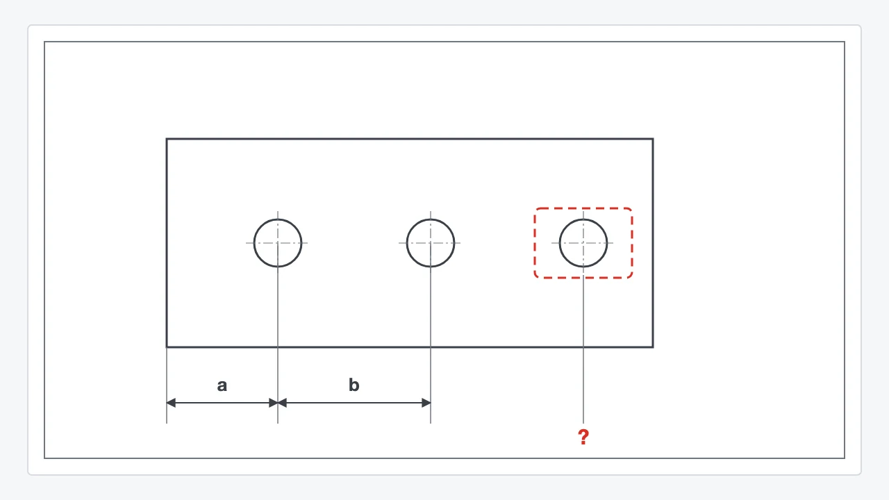
This is the most frequent comment. If even one dimension needed for machining is missing, that part cannot be made.
The ones most easily overlooked are dimensions that can be calculated from other dimensions. The designer works it out in their head and decides “they will be able to tell”, but the machinist works to the value indicated, not to a calculated result. A drawing that makes someone calculate hands the possibility of a calculation error to the supplier.
- Is every dimension needed for machining entered directly?
- Are the position, diameter and depth indicated for every hole?
- Do chamfers, radii, draft angles and other shape-defining features carry an indication?
- Has any dimension deleted in a design change been left as a blank gap?
Are there duplicate dimensions or a closed dimension chain?
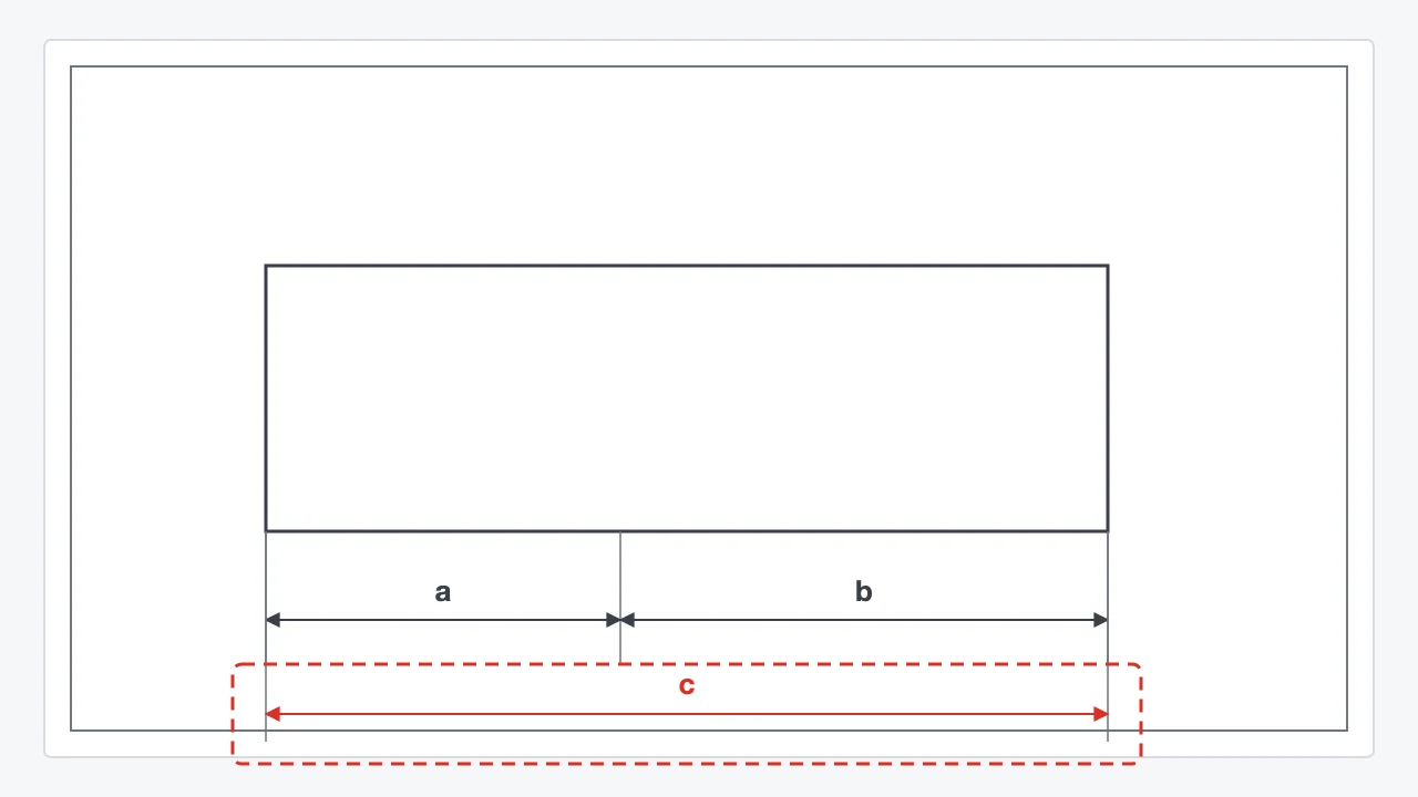
Dimensions are a problem not only when there are too few but also when there are too many. If the same distance is indicated in two places, which one takes priority is undefined. Once tolerances are taken into account, it may even be impossible to satisfy both at once.
The case that arises most often is the closed chain: entering every individual dimension and then the overall length as well. The individual tolerances stack up and contradict the tolerance on the overall length. Deciding what is the datum and what is left to fall out of the others is the designer’s job.
- Is the same distance indicated in two or more places?
- Is the chain of dimensions closed? If it is, has one of them been made a reference dimension?
- Are the datum faces and lines consistent throughout the drawing?
Do the tolerance indications hold up?
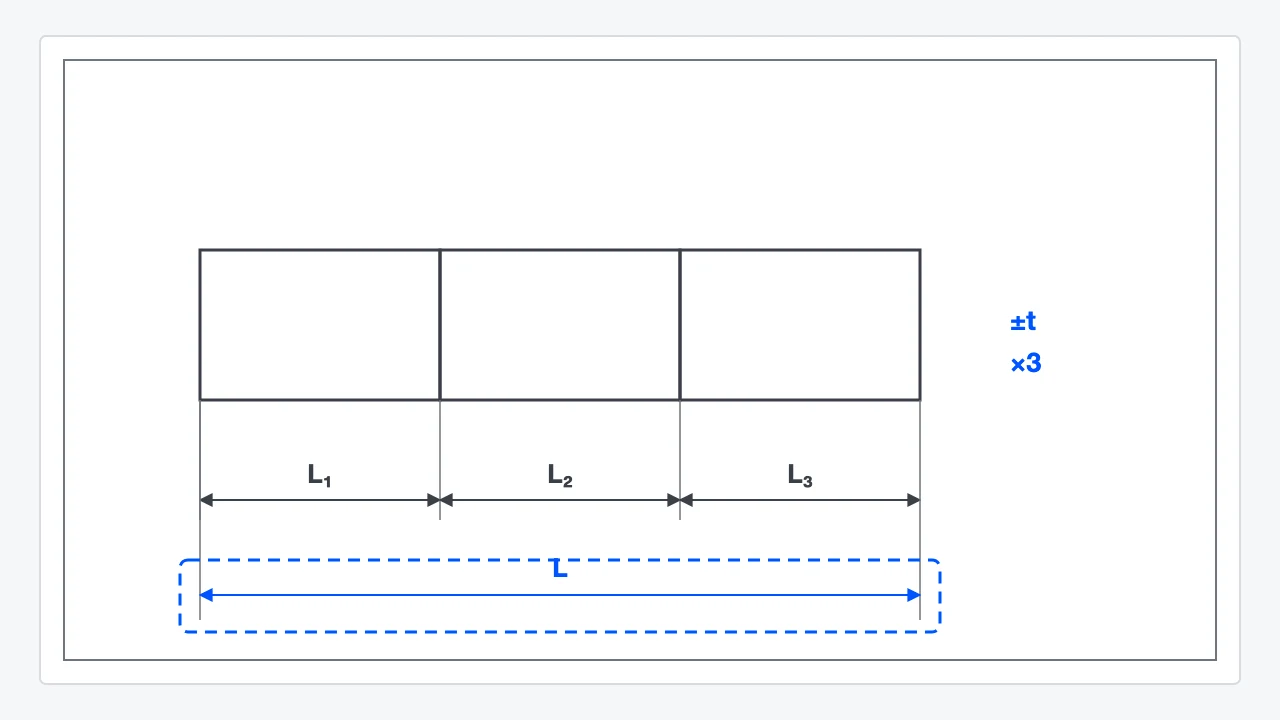
With tolerances, the problem is less often an omission than an indication that does not hold up.
One issue is stack-up. Even when individual dimensions are within tolerance, lining them up in series makes the total error larger than any of them individually. The reason something only turns out not to fit at assembly is this structure. For dimensions involved in assembly, you have to trace the path along which tolerances stack up.
The other issue is over-specification. The tighter the tolerance, the more operations and inspections are added. Check that tight tolerances are applied only where they are functionally necessary.
- Is the scope of the general tolerance stated explicitly in the title block or the notes?
- For dimensions involved in assembly, has the path along which tolerances stack up been checked?
- Are the datums for geometric tolerances defined, and consistent across the drawing?
- Are tight tolerances limited to the places that functionally need them?
Items to verify against the 3D model and the BOM
Next, cross-checking that drawing against other information.
Do the 3D model and the drawing agree?
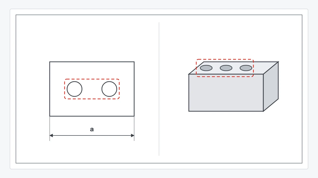
You correct the 3D model and forget to update the drawing, or the other way round. Projected views update automatically, but manually entered dimension values, notes and symbols do not follow, so you end up with a drawing whose shape is new and whose numbers are old.
The same structural problem arises between the assembly drawing and the part drawing. Only one of them is corrected, and it is released without anyone noticing.
- Are the projected views on the drawing generated from the latest 3D model?
- Do manually entered dimension values match the actual dimensions of the model?
- Do dimensions shared between the assembly drawing and the part drawing agree?
- Has the content of the design change been reflected in every drawing it affects?
Does it agree with the BOM and the accompanying information?
If the drawing and the bill of materials are out of step, the wrong part gets ordered against a correct drawing.
- Do the drawing number, part number and revision mark match the BOM?
- Do the material and surface treatment indications match between the drawing and the BOM?
- Do the quantities match between the assembly drawing and the BOM?
Items to verify against in-house rules and standards
Finally, whether it follows your own and the industry’s conventions.
Are the title block, the notes and the revision block filled in?
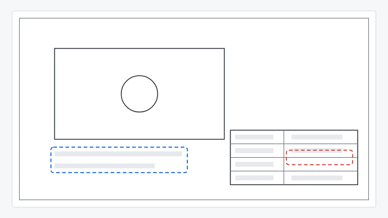
It is unglamorous, but if it is missing, the downstream processes stop. Material, surface treatment, the general tolerance indication, scale, projection method, revision history. If these are released blank, the supplier either has to ask, or has to guess at your standard and proceed.
- Are all the fields of the title block filled in?
- Are the material, surface treatment and heat treatment indicated?
- Are there default indications for general tolerance and surface roughness?
- Does the revision block carry the content of this change and its date?
- Are blanket notes on deburring, chamfering, cleaning and the like included?
Does the drawing follow your in-house drafting rules?
Even for the same part, the way the drawing is produced varies from person to person. The number of projected views, how sections are taken, which view a dimension goes on. Readability is part of quality, and a drawing that is hard to read invites misreading.
This area is not so much an industry-wide convention as each company’s own rules. If you have an in-house drafting standard, check the drawing against it. If there is none, or it has been left un-updated for years, that is where you have to start.
Putting the checklist into practice
What to settle first is not values but “our own drawing rules”
In the Sheet Metal Design Checklist the discussion started from “where do we measure from?”, and in the Machining Design Checklist from “which tools and equipment do we assume?”; for plastics it is “where do we split the mould?” For 2D drawings, what the discussion stalls on is whether your own drawing rules are written down.
How dimensions are entered, the format of the title block, the way notes are written — all of them differ by company. It is not that there is no industry standard; it is the result of each company building up a practice that suits its own products and its own customers. To build a checklist, you first have to write out these tacit rules.
- Take stock of the items most often commented on, using drawings that were actually released
- Pick a few examples of a “good drawing” and put into words why they are good
- Identify the items on which people’s judgements diverge, and settle them in-house
Separate the items that automate well from the ones that do not
The check items for 2D drawings split sharply by how easily they can be automated.
What automates well are items that can be judged by whether something exists. Whether the mandatory fields of the title block are filled in, whether the revision block has an entry, whether there is a general tolerance indication. A formal check picks these up reliably.
What does not automate well are items where “absent” is sometimes correct. Missing dimensions are the prime example. When a dimension is absent from a drawing, whether it was missed or is correctly omitted depends on what the shape is. Within an assembly drawing, for instance, it can be correct to omit a dimension that is given on the part drawing. Flagging that uniformly as a “missing dimension” would reject correct drawings in bulk.
In other words, judging a missing dimension requires a stage of interpreting what the lines drawn on the drawing represent. Only once you can read “this shape is a sheet metal part” or “this is a slot, and this width and that width mean the same thing” is it determined which dimensions are required. This is the heart of what makes 2D verification hard.
The other awkward point is whether an automated check can recognise that it did not know. If it can honestly report “I could not judge this” for what it could not judge, it can be operated. What is dangerous is missing something without noticing that you did not understand it. When you introduce an automated check, confirm not only the detection rate but how “cannot judge” is handled.
Visual checking has its limits
A single drawing carries dozens to well over a hundred dimensions, and dozens of drawings are released every day. A model in which people check every one of them will hit its limit somewhere. And when it does, people decide “this part is probably fine” and skip it — and what is skipped is what gets missed.
On top of that there is the structural problem that only a few people can do the verification. The ones who can judge whether a drawing is good are experienced designers, and their time is the scarcest of all. If the items that can be judged formally are shifted towards automation, their time can be redirected to the judgements only people can make, such as design intent and functional requirements.
What to automate and what people review: we have organised that thinking in What Is AI Drawing Inspection? How Manufacturers Automate Design Verification to Reduce Errors and Checking Hours.
Frequently asked questions about 2D drawing verification
Which should come first, verifying the 2D drawing or verifying the 3D model?
The 3D model comes first. Whether the shape can be machined and assembled can be judged at the 3D stage, and problems found there can be fixed before the drawing is produced. If a shape problem turns up after the drawing has been produced, you end up fixing both the drawing and the model. Think of 2D drawing verification as the step, after the shape is fixed, that asks “does this drawing communicate correctly?”
Can we not have generative AI read the drawing and check it?
It is usable for summarising the content of a drawing, or checking how a note is worded. However, in verification — where every single dimension has to be read without a miss — some services cannot perform a rigorous check. Before adopting one, confirm on your own drawings whether anything is missed.
Can we not automate drawing checks with macros written in-house?
Formal items — whether the mandatory fields of the title block are filled in, for example — can be automated well enough with macros. What is hard are the items that require interpreting the shape. The more unusual the shape, the more unforeseen cases arise and the macro stops working: we hear that from several companies. Automating the formal checks with macros first, and considering other means for the areas that need interpretation, is the realistic split.
How many verification items should we have?
We would suggest not making the number a target. Start by collecting drawings on which comments were actually raised in your own company and counting what kind of comment came up how many times. A handful of items at the top should account for most of the total. Items derived from that become a list people actually use on the floor.
If we introduce automated checking, will senior engineers’ verification become unnecessary?
No. Items that can be judged formally can be automated, but the validity of design intent and functional requirements cannot be covered by automated judgement. The aim is to free senior engineers’ time from formal checking and redirect it to the judgements only people can make.
Summary
Design verification of a 2D drawing looks at different things from verification of a 3D model. 3D is “do not make the wrong thing”; 2D is “does it communicate correctly?” Only when both are in place is the design in a state that can be handed to manufacturing.
The items can be organised into three layers: agreement within the drawing, agreement with the 3D model and the BOM, and agreement with in-house rules and standards. The most frequently raised — missing and duplicate dimensions — belong to the first layer; discrepancies between assembly and part drawings to the second; the title block and drafting style to the third.
When you think about automation, divide the items into “those that can be judged by whether something exists” and “those where absent is sometimes correct”. The former can be automated reliably; the latter require interpreting what the geometry is.
As it happens, we publish free of charge a list of the basic items to check on the 3D model side for sheet metal and machining (milling and turning). They are not 2D drawing verification items as such, but the way of organising them — an item name together with what it prevents — can be used as a template when you build your own verification checklist.
If you would like to discuss 2D drawing verification, or checking a drawing against the 3D model, you are welcome to contact us.
This article was written by WOGO Inc., a University of Tokyo-originated startup developing systems for design verification, automated drawing inspection and design/drafting automation in manufacturing using 3D, CAD and AI technologies.