



3D CAD
Rework
Manufacturing DX
September 21, 2026
Machining Design Checklist: The Milling and Turning Rules to Check First
 Updated on 2026/09/21
Index
Rework on machined parts, just as on sheet metal, surfaces only after machining has started. “A tool cannot get into this corner.” “This hole is too deep to hold the accuracy.” Every one of them could have been caught at the design stage.
A machining design check means confirming, before release, that the shape you have designed can be cut with the tools and machines you assume, and that the accuracy and the man-hours hold up. This article explains what machining design rules are actually derived from, and works through the items that most often lead to rework, split into milling and turning.
As in the sheet metal article, the focus here is on what to check and why, rather than on specific threshold values. Machining thresholds change with tool diameter, tool length and the capability of the machine. Understanding the reasoning that fixes a value is more useful on a shape you are seeing for the first time than memorising the value itself.
A complete list of the basic check items for sheet metal, milling and turning is published free of charge as the Basic Manufacturing-Limit Check Rules (33 items for sheet metal and machined parts). Treat this article as the explanation of the thinking that makes that list usable.
Key points of this article
- Unlike sheet metal, where the question is whether the material can withstand deformation, machining design rules are a restatement of “can the tool reach, and will the tool hold up?” If you can picture the shape and the length of the tool, you can judge a shape you are seeing for the first time
- There are two main things to look at. For milling, tool diameter and tool length; for turning, the ratio of diameter to length — these settle almost every rule
- Machining rarely stops at “it cannot be made”. More often, a special tool or an extra setup makes it “possible, but more expensive and slower”. When a quotation differs from what you expected, the reason is usually in the shape
- Specific thresholds change with the tools and the equipment at your machining supplier. When you build an in-house standard, what to decide first is not the values but “which standard tools and equipment do we assume?”
Machining: what the designer actually decides
Machining creates a shape by removing unwanted material from stock such as a block or a round bar, either with a rotating tool (a milling cutter or a drill) or with a cutting tool applied to rotating stock (a lathe tool). Where sheet metal makes a shape by deforming a single sheet, machining makes a shape by taking material away.
In machining design, the designer decides roughly the following four things.
- Material: S45C (carbon steel), SS400, SUS304, A5052 / A7075 (aluminium), C3604 (brass), plastics and so on. On top of strength, corrosion resistance and cost, how easily it cuts (machinability) drives the man-hours
- Stock form and machine: cutting from a block means milling (a machining centre); cutting from a round bar means turning. This choice changes which rules apply from that point on
- Machining direction and datum face: which face is set down and clamped, and from which direction the tool enters. Every direction the tool has to enter from is another setup (re-clamping the workpiece)
- Tolerances and finish: where, and how much accuracy and surface roughness, you require. Whether these are narrowed down to the places that need them decides the number of operations and the inspection hours
The difference from sheet metal: deforming versus removing
In the Sheet Metal Design Checklist, bends were organised around “will it sit in the machine?” and holes around “can it be punched, and will it stay undistorted?” The constraints centred on whether the sheet, as a material, could withstand deformation.
In machining, the centre of the constraints moves to the tool. A tool has a diameter and a length, and because it cuts by rotating, internal corners always end up rounded. Anywhere the tool cannot reach cannot be cut, and a tool that is thin and long deflects and vibrates while it is cutting. Almost every machining design rule is derived from this “shape and rigidity of the tool”.
Milling and turning start from different points
Milling applies a rotating tool to a clamped workpiece. The starting point here is tool diameter and tool length. The width of a slot and the radius of an internal corner come from the tool diameter; the depth of a pocket or a hole comes from the tool length.
Turning applies a cutting tool to rotating bar stock. The starting point here is the ratio of diameter to length. A long, slender shaft deflects while it is being cut, and a deep bore is beyond the reach of the boring bar that supports the insert. The same comment — “it is too deep” — is about tool length on a mill, and about length relative to diameter on a lathe.
Why machining checks lead directly to rework
In machining, the shape and the motion of the tool become the limits of the shape itself. An end mill is round, so an internal corner keeps a radius of at least the tool radius; a drill that is thin and long wanders and bends; a lathe tool is supported less and less the further it goes into a bore. Even if the designer can draw it, a shape that a tool physically cannot enter or withstand cannot be machined.
The other constraint is setup. A tool only enters from one direction, so a part with machined faces in several directions has to be unclamped and re-clamped more often. Every additional setup adds another layer of positioning error, and more man-hours.
What differs from sheet metal is that machining comparatively rarely stops at “it cannot be made”. Most cases can be made somehow — preparing a special tool, moving the part to a 5-axis machine, adding EDM. As a result, the feedback comes back not as “we cannot make this” but as “this is the quotation you get”. Because the drawing passes, the cost rework is noticed late.
Machining checks therefore have to cover both “shapes that cannot be made” and “shapes that can be made but cost more”. We have organised the cost structure of a single design change in Rework Costs on the Manufacturing Design Floor, and the Arguments Around 3D and 2D Design Verification.
Milling: the design rules to check first
Milling is viewed from the standpoint of “can the tool reach?” and “will the tool hold up?” Here we take up the four representative items in which the two starting points — tool diameter and tool length — appear most directly.
Is there an internal corner radius, and is it too small?
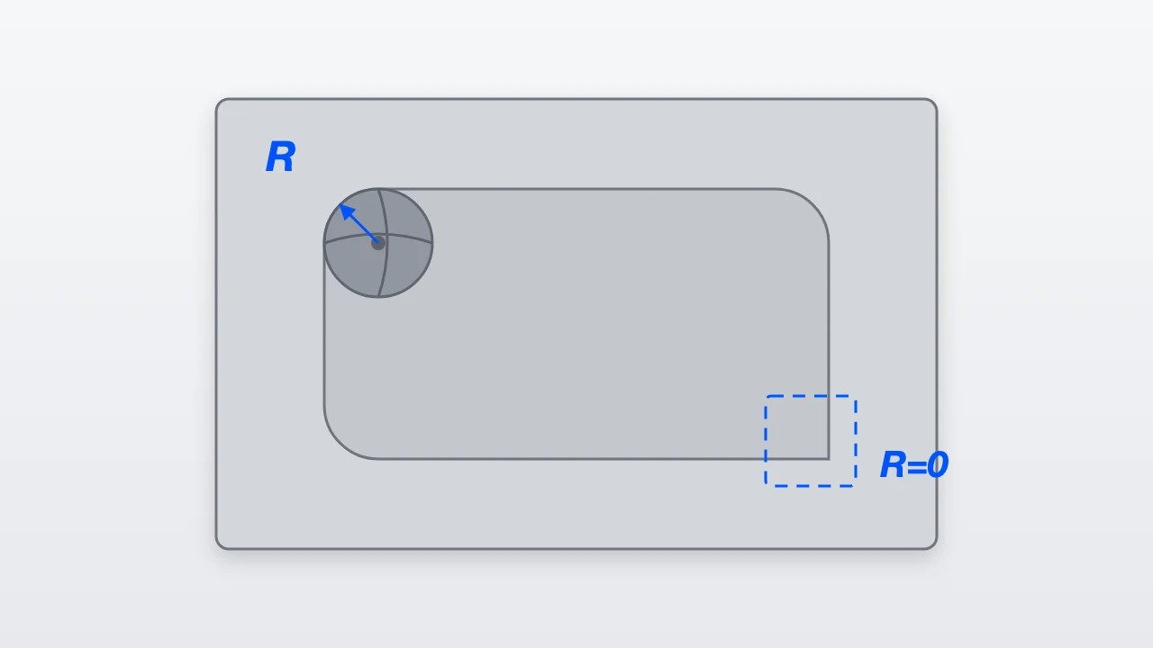
An end mill is cylindrical, so the vertical internal corner of a pocket or a step always keeps a radius of at least the tool radius. If you model that corner as a sharp edge in 3D CAD, it cannot be cut as modelled. If a sharp corner is genuinely required, the design moves to EDM, or to adding an undercut at the corner to clear it, and an operation is added.
The smaller the internal corner radius, the thinner the tool that is required. A thin tool cannot cut deep, deflects easily and breaks easily. The value of an internal corner radius is not a matter of appearance: it decides how many tools, and how much time, that pocket takes to cut.
- Do the internal corners (corners of less than 180°) have a corner radius?
- Is that corner radius one that the standard tooling at your machining supplier can cut?
- Have you avoided making the corner radius exactly equal to the tool radius? (When the whole circumference of the tool engages at once, vibration becomes likely, so it is usual to make it slightly larger)
Is the slot or pocket wide enough for the tool, and is it too deep?
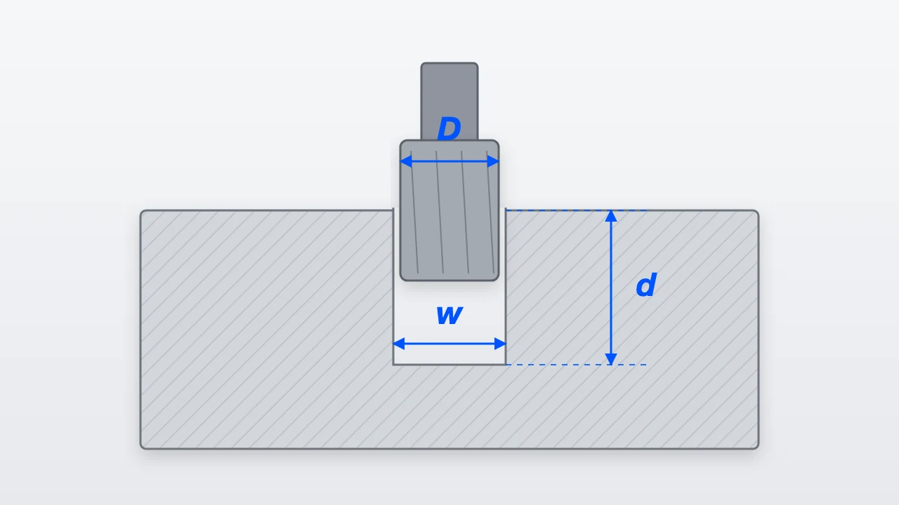
A slot cannot be cut unless its width is at least the diameter of the tool used. A narrow slot demands a thin tool, and a thin tool cannot cut deep. In other words, a slot that is both narrow and deep is the hardest shape of all.
Pocket depth works the same way. A deep pocket needs a long tool (one with a large stick-out), and a long tool deflects so the dimensions do not come out, while chatter (vibration) spoils the surface. “Width” and “depth” are not looked at separately; they are looked at as a ratio.
- Does the slot width work with the standard tool diameters at your machining supplier?
- Is the depth of the slot or pocket too great relative to its width (the tool diameter)?
- If a deep pocket is required, is there a workaround — breaking through the bottom, splitting the part, or widening it?
Are holes and tapped holes too deep?
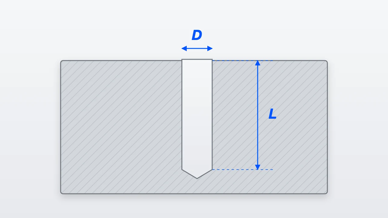
The difficulty of a hole depth is settled by its ratio to the diameter (L/D). In a deep hole the chips do not evacuate well, the drill wanders and bends, and positional accuracy and straightness deteriorate. Peck drilling or a gun drill can cope, but operations and time are added.
Tapped holes are stricter still. Beyond a certain multiple of the diameter, the effective thread depth adds almost no strength, and going deeper only raises the risk of breaking the tap. “Deep, just to be safe” does nothing for strength and everything for cost.
- Is the hole depth within the guideline your machining supplier gives for that diameter?
- Is the depth of the tapped hole excessive for the clamping strength actually required?
- Is the deep hole genuinely necessary? Are there options such as breaking through, machining from the other side as well, or increasing the diameter?
Are holes too close to a side or bottom face?
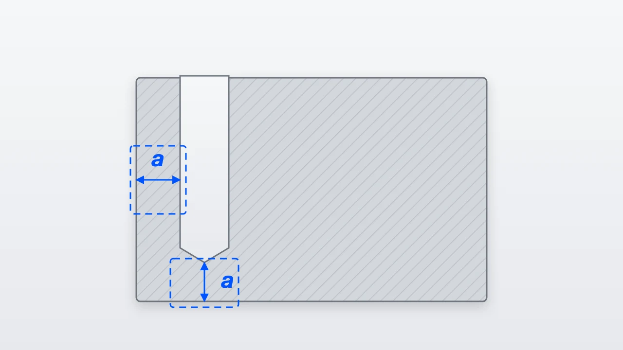
If a hole sits too close to the side or bottom face of the workpiece, the material left behind becomes thin. A thin wall deforms under the cutting force: the hole distorts, burrs appear, and in the worst case the tool breaks through. The distance between the bottom of a blind hole and the bottom face of the workpiece is the same — if that floor is thin, the underside bulges.
This is the same topic as “the distance from a hole to the edge” in sheet metal, but the reason differs. In sheet metal the material gives way during shearing; in machining a thin wall deforms under the cutting force.
- Is enough material left between the hole and the side face?
- Is enough material left between the bottom of a blind hole and the bottom face of the workpiece?
- Are there slots or pockets close to the hole that thin out the material around it?
There is more to check in milling than these four items
The four items above are the ones in which the starting points — tool diameter and tool length — show up most plainly. A real check also covers how the hole diameter is chosen, the direction of a hole, the relationship between the size of the workpiece and the equipment, and how far the tool can reach (undercuts and setups): some nine basic items for milling alone. The list of the items, and what each of them prevents, is set out in the Basic Manufacturing-Limit Check Rules.
Turning: the design rules to check first
Turning is viewed on two counts: “the ratio of length to diameter” and “can the cutting tool get in?” Here we take up the two representative items in which those two counts appear most directly.
Is it too long relative to its diameter?
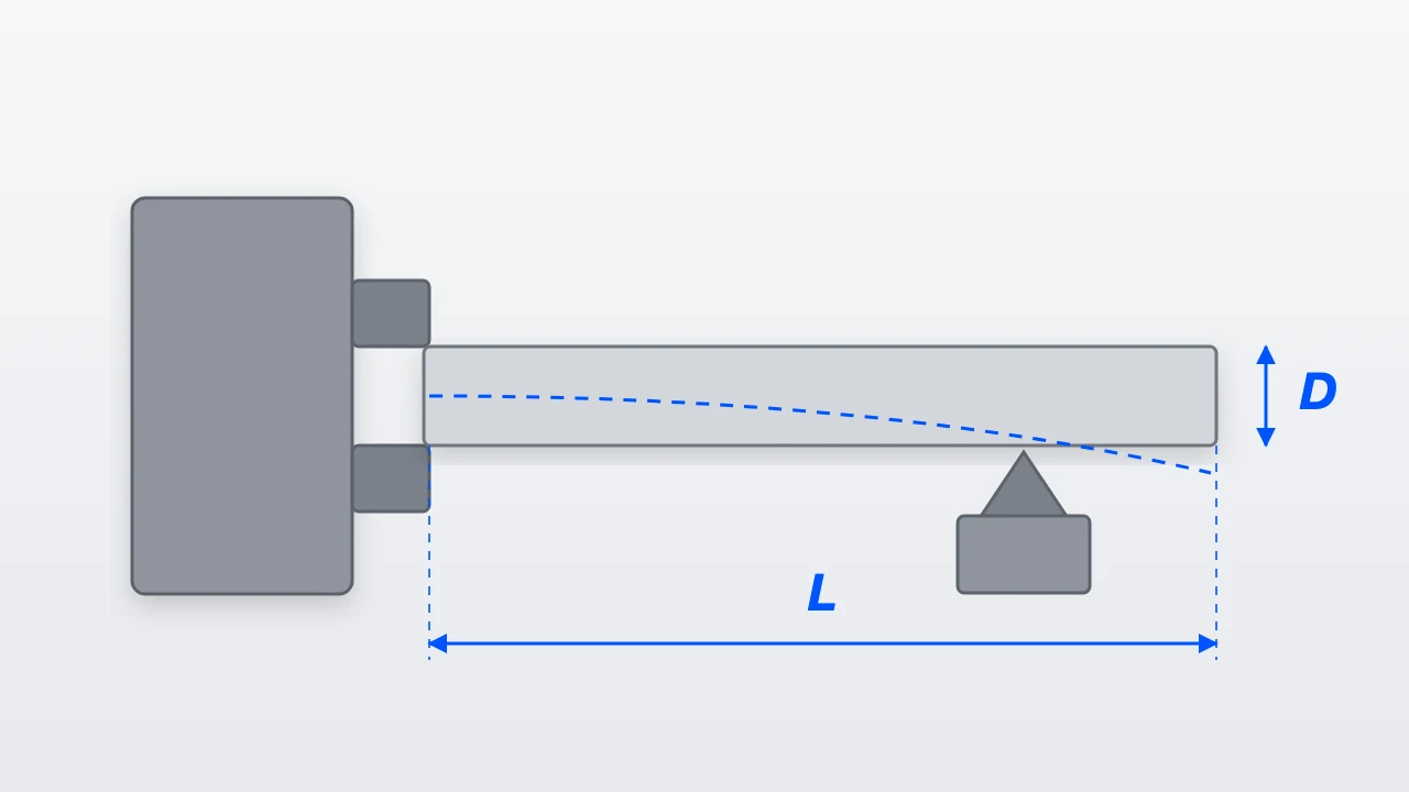
On a lathe, the workpiece is gripped in a chuck on one side and rotated while a cutting tool is applied. A shaft that is long relative to its diameter deflects at the free end under the cutting force, so the diameter varies from place to place (taper) and chatter spoils the surface. A tailstock or a steady rest can support it, but that adds setup, and there is still a limit.
- Is the overall length of the shaft within the guideline your machining supplier gives for that diameter?
- If a long shaft is required, is there an option to leave a thicker section part-way along, or to split it and join the pieces?
Bore: can the boring bar get in, and is it too deep?
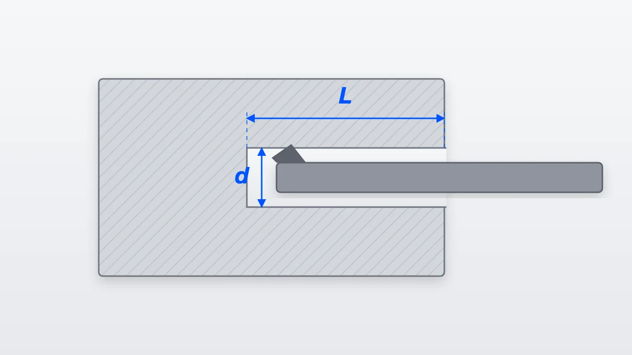
Boring on a lathe is done by inserting a boring bar into the hole. The bar has a shank of a certain thickness, so a bore that will not accept it cannot be cut. Beyond the diameter a drill can produce, the hole has to be opened out to a diameter the bar fits into, or neither the bore finish nor an internal groove can be machined.
Depth follows the same logic. The bar can only enter from the mouth of the hole, so the deeper the bore, the further the shank has to stick out, and it deflects so the accuracy does not come out. A bore that is too deep for its diameter is structurally the same problem as a deep pocket in milling.
- Is the bore a diameter that a boring bar can be inserted into?
- Is the depth of the bore too great for that diameter?
- If a deep bore is required, could it break through so that it can be machined from both ends?
There is more to check in turning than these two items
The two starting points — the ratio of length to diameter, and how far the cutting tool can reach — appear in items beyond those above. The outside diameter (sections that are too thin, or a size that will not fit the equipment) and the distortion of a thin-walled section when it is gripped in the chuck are examples: some six basic items for turning alone. These too are listed in the Basic Manufacturing-Limit Check Rules.
Related items worth checking at the same time
With machined parts, the man-hours change not only with whether the shape can be cut, but also with how the requirements are specified.
- Over-specified tolerances: the tighter the tolerance, the more operations (finishing, grinding) and inspection are added. Check that tight tolerances are attached only where they are functionally required
- Over-specified surface finish: specifying a fine surface finish on every face can multiply the machining time several times over. Limit it to the faces that need it, such as contact faces and sealing faces
- Chamfer and deburring instructions: machined parts produce burrs on almost every edge. Look for a blanket instruction such as “C0.5 all round” or “no burrs”, and for explicit identification of the places where burrs are functionally unacceptable
- Material and machinability: stainless steel work-hardens and wears tools, while aluminium cuts easily but distorts in thin sections. The same shape may or may not be feasible depending on the material
- Shapes that combine milling and turning: a round part with a keyway or a cross hole moves from turning to milling for another setup. A multi-tasking machine does it in one, but that depends on the equipment at your supplier
Much of this cannot be judged from the shape of the 3D model alone, and is left to the instructions on the 2D drawing and to agreement with the machining supplier. Managing what is checked on the 3D model separately from what is conveyed by the drawing and its notes reduces gaps in the review.
Putting a checklist into operation
As we wrote in the sheet metal article, creating a checklist is not the hard part. The hard part is keeping it running without letting it become a formality. In machining, the discussion stalls at a different point than it does in sheet metal.
What to decide first is not the values, but the tools and equipment you assume
Almost all machining thresholds are derived from the tool. The lower limit for an internal corner radius comes from the radius of the standard tool, the lower limit for a slot width from the diameter of the standard tool, and the upper limit for the depth of a pocket or a hole from the stick-out of the tool. In other words, unless you decide which tools count as “standard”, the values cannot be settled.
On top of that, the same shape is judged differently depending on whether it is made by milling or turning, and on 3 axes or 5. Unless “which machine is this part assumed to be made on?” has been settled, a shape can violate one rule and pass another, and the list stops working as a list.
- Decide, together with your machining supplier, the set of tool diameters and tool lengths you treat as “standard” in-house
- Decide up front, for each part, the machine you assume (milling / turning / multi-tasking, 3-axis / 5-axis)
- Attach to each item a note of which tool or which machine the value is derived from
In sheet metal the discussion stalled on “where do we measure from”; in machining it stalls on “which tools and equipment do we assume”. Put the other way round: once that is agreed, the values can be filled in by asking the machining supplier.
Assume that values change from supplier to supplier
The tool crib and the equipment differ from one machining supplier to the next. Fixing a single value makes it excessively strict for one supplier and too loose for another. Structuring it so that the items are shared and the values are parameters per supplier keeps the standard from breaking down as your supplier base grows. This structure is the same as in sheet metal.
Visual checking has its limits
Milling and turning together already come to well over a dozen basic check items, and several dozen once the related items are included. What is more, many machining items combine several dimensions in a single judgement — an internal corner radius against a tool diameter, a depth against a diameter. Having people visually check every item on every part is not realistic, and the more experienced the designer, the more they decide “this one is fine” and skip ahead. And what is skipped is what gets missed.
Anything whose judgement can be written in terms of shape and numbers can be judged automatically from the 3D model. The presence of an internal corner radius, the slot width, the ratio of hole depth to diameter, the distance from a hole to a side face, and the ratio of shaft length to diameter all fall within that range. Judgements that touch design intent, on the other hand — “is this tolerance really necessary?”, “is this thin wall functionally unavoidable?” — cannot be read from the shape alone and remain with people.
What to automate and what people should review — we cover that division of labour in detail in What Is AI Drawing Inspection? How Manufacturers Automate Design Verification to Reduce Errors and Checking Hours.
Start by comparing what ought to be on your own checklist against the list of basic items.
Frequently asked questions about machining design checklists
How large should the internal corner radius be relative to the tool diameter?
Rather than making it the same as the tool radius, it is usual to make it slightly larger. If the internal corner radius is exactly the tool radius, the whole circumference of the tool engages the material at once and vibration becomes likely. Decide the specific value by working back from the tool diameters your machining supplier keeps as standard. Note as well that the smaller the internal corner radius, the thinner the tool required, and the shallower the depth that tool can cut.
How deep can a hole be and still be machined normally?
Judge it by the ratio of depth to hole diameter (L/D). The guideline ratio changes with the type of drill, the material and the equipment at the supplier, so confirming it with the machining supplier is the reliable route. The larger the ratio, the worse the chip evacuation, and the more the drill wanders, degrading position and straightness. What the designer can do is consider the options first: breaking through, machining from both ends, or increasing the diameter.
Is it the designer who decides whether a part is milled or turned?
In practice it is settled by the form of the stock (block or round bar) and by the main shape (whether it is rotationally symmetric). However, for parts that have both characteristics — a round part with a keyway or a cross hole — the rules that apply and the man-hours change depending on which is taken as the main process and whether a multi-tasking machine is assumed. Unless at least “the machine we assume” is decided at design time, the basis for the check is not fixed.
Can the CAM function or the standard functions of 3D CAD judge whether a shape can be machined?
CAM is a tool for creating tool paths — how to cut a given shape — and judging from the design side that “this shape should not be cut” is not its proper role. It can reveal places a tool cannot reach when the tool path is generated, but that is work on the manufacturing side, not a check at the design stage. Bringing the machining supplier’s rules in and judging against them at the design stage requires a separate mechanism.
If we introduce automated design verification, will human checking become unnecessary?
No. Rules that can be written in terms of shape and numbers — internal corner radii, slot widths, depth ratios, remaining wall thickness, L/D — can be automated, but judgements of design intent such as “is this tolerance necessary?” or “is this thin wall functionally unavoidable?” cannot be covered by automated judgement alone. You need to design the division of roles: what is automated and what people review.
Summary
A machining design checklist is the shape and rigidity of the tool, and the capability of the machine, translated into the designer’s language. For milling, “can the tool reach, and will the tool hold up?”, in terms of tool diameter and tool length; for turning, the ratio of length to diameter. Hold on to these two viewpoints and the individual items can be derived from the reasons behind them.
Unlike sheet metal, machining often does not stop at “it cannot be made” but comes back in the form of “it can be made, but it costs more”. That is exactly why a check before release goes straight to cost.
And specific thresholds change with the tools and the equipment at your machining supplier. What should be decided first when standardising in-house is not the values, but “which standard tools and machines do we assume?”
Once the items reach several dozen and more of them combine several dimensions in a single judgement, a model in which people visually check every one of them hits its limit. Shift the judgements that can be written in shape and numbers towards automation, and let people spend their time on the judgements that touch design intent. The design quality of machined parts is determined by how you design that division of labour.
The full list of 33 basic check items for sheet metal, milling and turning, including the representative items covered in this article, is available in the resource below. Please use it to take stock of your own checklist.
If you would like to discuss standardising design rules for your own machining suppliers, or checking them automatically from 3D models, you are also welcome to contact us.
This article was written by WOGO Inc., a University of Tokyo-originated startup developing systems for design verification, automated drawing inspection and design/drafting automation in manufacturing using 3D, CAD and AI technologies.