



3D CAD
Rework
Manufacturing DX
August 12, 2026
Sheet Metal Design Checklist: The Bend and Hole Rules to Check Before Release
 Updated on 2026/09/21
Index
Most rework on sheet metal parts surfaces only after fabrication has started. “That bend is difficult to form.” “This hole will distort.” Both could have been caught at the design stage.
This article organises the points to check in sheet metal design into two groups: bends and holes. Rather than specific threshold values, it focuses on what to check and why. Thresholds change with material thickness, material grade and the equipment at the fabricator, so understanding the reasoning behind a value lasts longer in practice than memorising the value itself.
The figures in this article are taken from the illustrations of the check items that WOGO actually uses for automated design verification on 3D models.
Key points of this article
- Sheet metal design rules are not design etiquette; they are a restatement of the physical constraints of the forming equipment. Once you understand the reasons, you can judge a shape you have never seen before
- There are two main things to look at. For bends, “will it sit in the machine?” For holes, “can it be punched, and will it stay undistorted?”
- Relief is not a separate topic; it appears within both bends and holes. Check it at the root of a bend and at holes on the bend line
- Specific thresholds differ by fabricator. When you build an in-house standard, the discussion stalls first not on the values, but on the definition of the datum — where you measure from
What does sheet metal design actually decide?
Sheet metal design means resolving a part into a shape that can be produced by bending a single flat sheet, and deciding the material, the thickness, the flat pattern and the bend sequence. Unlike machining or moulding, drawing the finished three-dimensional shape alone does not give you a part: the shape must always be able to return to the flat blank it is bent from.
Four things are decided in sheet metal design.
- Material: SPCC (cold rolled steel), SPHC (hot rolled steel), SUS304, A5052 (aluminium) and so on, chosen for strength, corrosion resistance, cost and how readily the material bends
- Thickness: not an arbitrary value, but one of the stock thicknesses available for that material. For SPCC, 0.5 / 0.8 / 1.0 / 1.2 / 1.6 / 2.0 / 2.3 / 3.2 mm are the everyday range
- Flat pattern: the outline of the sheet before bending. Bend lines, reliefs and hole positions all appear here
- Bend sequence and datum: the order the bends are formed in, and the face used to locate the work. Choose a sequence the tooling cannot reach later and the part is unfabricable, even though the solid geometry itself is valid
Flat length changes with thickness and bend radius
Flat length is the first thing that catches people out. When a sheet is bent, the outside of the bend is stretched and the inside is compressed. Between them lies a surface that is neither stretched nor compressed: the neutral axis.
Flat length is set by the length of that neutral axis. So even when the finished dimensions are identical, changing the thickness or the inside bend radius changes the length of blank you need. The neutral axis does not sit at the middle of the thickness but closer to the inside, and how far in it sits depends on the material and the forming conditions. In practice the bend allowance held by the fabricator is what governs, and a calculated value pushed through from the design side will not match the parts that come back.
This property — that the value depends on the fabricator — applies in exactly the same way to the bend radii and relief thresholds covered below.
Thickness moves every rule that follows
Thickness is not only a strength parameter. Minimum bend radius, required flange height, minimum hole diameter, the distance from a hole to a bend line, the size of a relief — almost every sheet metal design rule is written as a multiple of thickness. Change from 1.6 mm to 2.3 mm and all of those thresholds move at once.
So deciding thickness on strength alone can make a shape that already worked impossible to fabricate. Whenever the thickness changes, it is worth running back through the check items below.
Why sheet metal design checks lead directly to rework
Sheet metal fabrication turns a flat sheet into a three-dimensional shape by punching and bending it. Unlike machining, material is not cut away from a block; a single sheet is deformed into shape. The order of these processes determines almost every sheet metal design rule.
- In the punching process, a punch and die shear the sheet. Holes that are too small, holes that are too close together and corners that are too sharp will either break the tooling or tear the sheet
- In the bending process, the sheet is placed on the die of a press brake and pushed down by the upper tool. A shape that will not sit fully on the die, or that interferes with the upper tool or the machine bed, simply cannot be loaded into the machine
In other words, sheet metal design rules are not a matter of “this is preferable”; they are the physical constraints of the forming equipment translated into the designer’s language. That is why memorising thresholds alone does not transfer to new cases, while understanding the reasons lets you judge shapes you have never encountered.
Drawings that do not respect these rules come back with comments from the shop floor after fabrication has begun. A single design change cascades into redesign, re-verification and re-ordering of the related parts. We have also covered the cost structure of rework in Rework Costs on the Manufacturing Design Floor, and the Arguments Around 3D and 2D Design Verification.
Design rules to check for bends
Bends are viewed from the standpoint of “will this shape sit in the machine?“
Is there a bend radius, and is it too small?
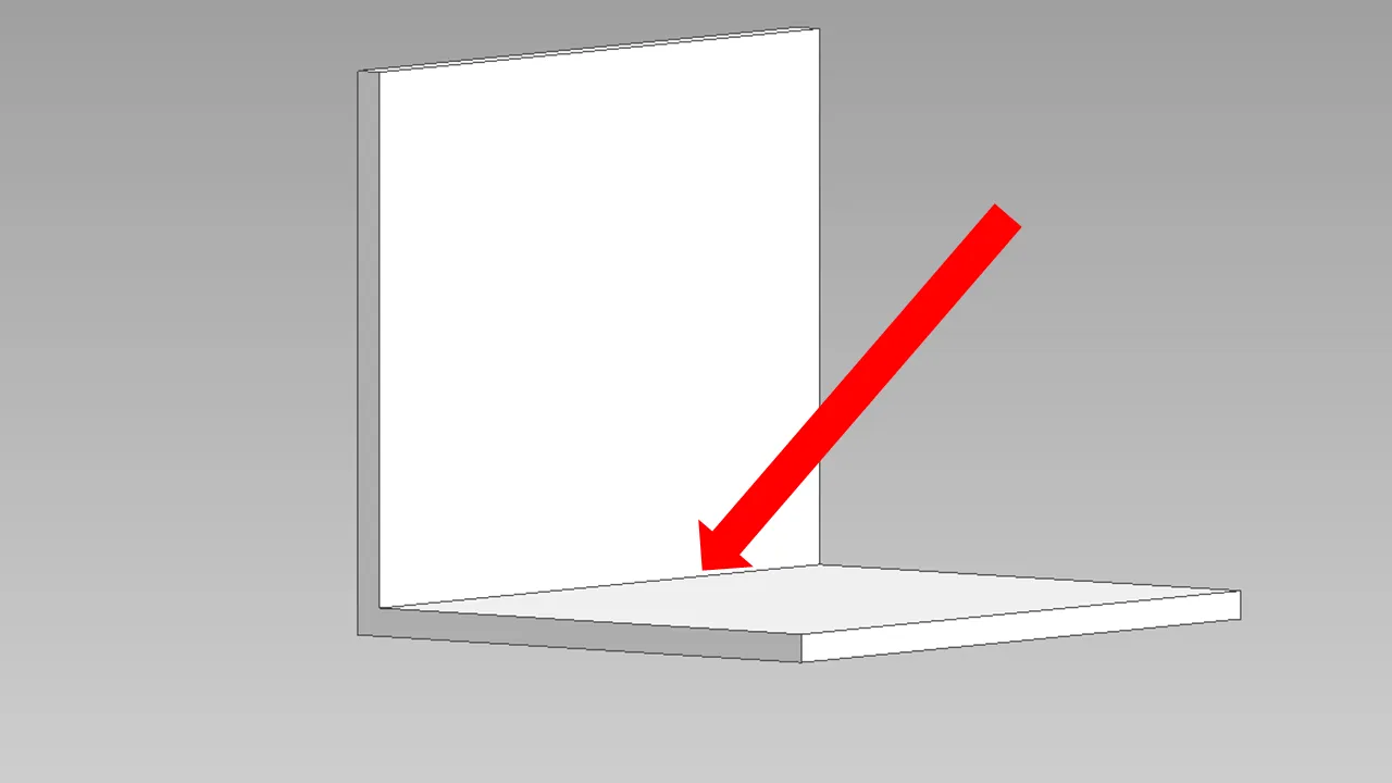
A bend always has a radius. If you model the corner as a sharp edge in 3D CAD, the part cannot be made as modelled. This omission is common in models built by extruding faces without using the sheet metal mode.
If the radius is too small, the force required for the bend exceeds what the machine allows. On the material side, cracks also become more likely.
- Is a fillet present at the bend?
- Is that radius one that the fabricator’s standard tooling can produce?
Is the flange height sufficient?
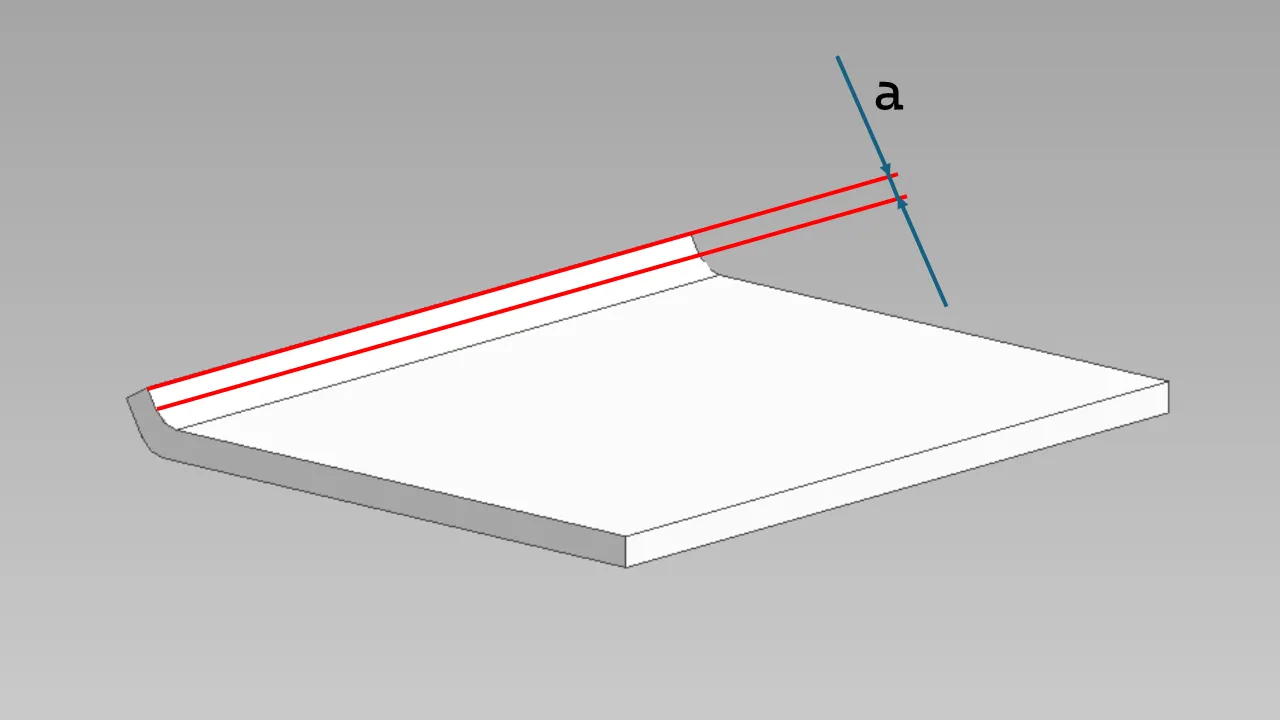
If the distance from the bend line to the edge is short, the sheet does not sit fully on the die and the bending force is not transmitted correctly. The result is an angle that does not come out as specified and dimensions that vary.
- Is the distance from the bend line to the edge secured?
- For edges cut at an angle, or edges whose width changes along the way, does it hold at the shortest point?
- If only part of the flange is short, could the angle fail to come out in that area alone?
Is there relief at the root of the bend and at the corners?
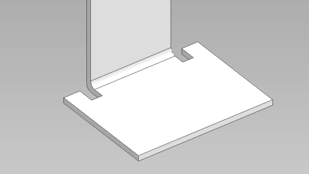
When you bend only part of a sheet (raising a tab), stress concentrates at the boundary between the bent and unbent areas, and the root is pulled in and deforms. Adding a notch at the root stops the deformation there. The same applies to a corner where bends in two directions meet: without relief, the material either overlaps or is pulled in.
Relief is not a question of “whether to add it”; it is a shape that decides where the deformation is absorbed. If you do not add it, the deformation appears somewhere the designer did not intend.
- Is there a notch at the root of a partial bend? Do its width and depth meet the fabricator’s criteria?
- Has the treatment of corners where adjacent bends meet been decided?
- Is that treatment consistent with the functions required of the part (strength, sealing, appearance)?
Is the material thickness uniform?
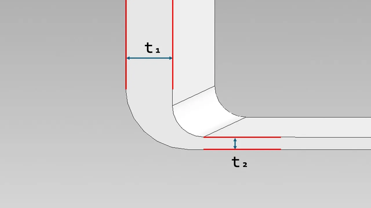
Sheet metal parts are made from a single sheet. A model with locally different thicknesses cannot exist as a sheet metal part. This happens when a model designed as a machined part is reused for sheet metal, or when faces have been edited individually.
Does the workpiece interfere with the machine?
Bends are formed one at a time, in sequence. At the moment a given bend is formed, what matters is where the already-bent portions project.
- Z bends (offsets): if the offset is small, the workpiece interferes with the upper tool and the die and cannot be loaded
- U channels: if the legs are tall and the width is narrow, the upper tool hits the workpiece on the final bend
- Long unbent edges: at the moment of bending they contact the machine bed or surrounding structure
Even though a drawing looks flat, during fabrication a three-dimensional shape moves inside the machine. Picture the bend sequence one step at a time and check where the workpiece projects at each step.
Is there a face to register against the back gauge?
When the workpiece is set up, it needs a reference face to push against the back gauge. A shape with no straight edge parallel to the bend line cannot be positioned. This occurs on parts whose entire outline consists of curves and angled edges.
Does it stay within the machine capacity and the limits of the material?
The force required for a bend is proportional to both the material thickness and the length of the bend line. Even when “the thickness is fine” and “the length is fine”, the product of the two can exceed the tonnage of the machine.
The material has limits too. Hard or heat-treated materials develop cracks or fractures at the bend. Whether you bend perpendicular or parallel to the rolling direction (the grain) also changes how easily the material cracks.
- Is the combination of thickness and bend length feasible on the fabricator’s equipment?
- Will the combination of material grade and thickness avoid cracking at that bend radius?
- For crack-prone materials, does the bend direction need to be specified relative to the rolling direction?
Design rules to check for holes
Holes are viewed on two counts: “can it be punched?” and “will it stay undistorted?“
Can it be punched?
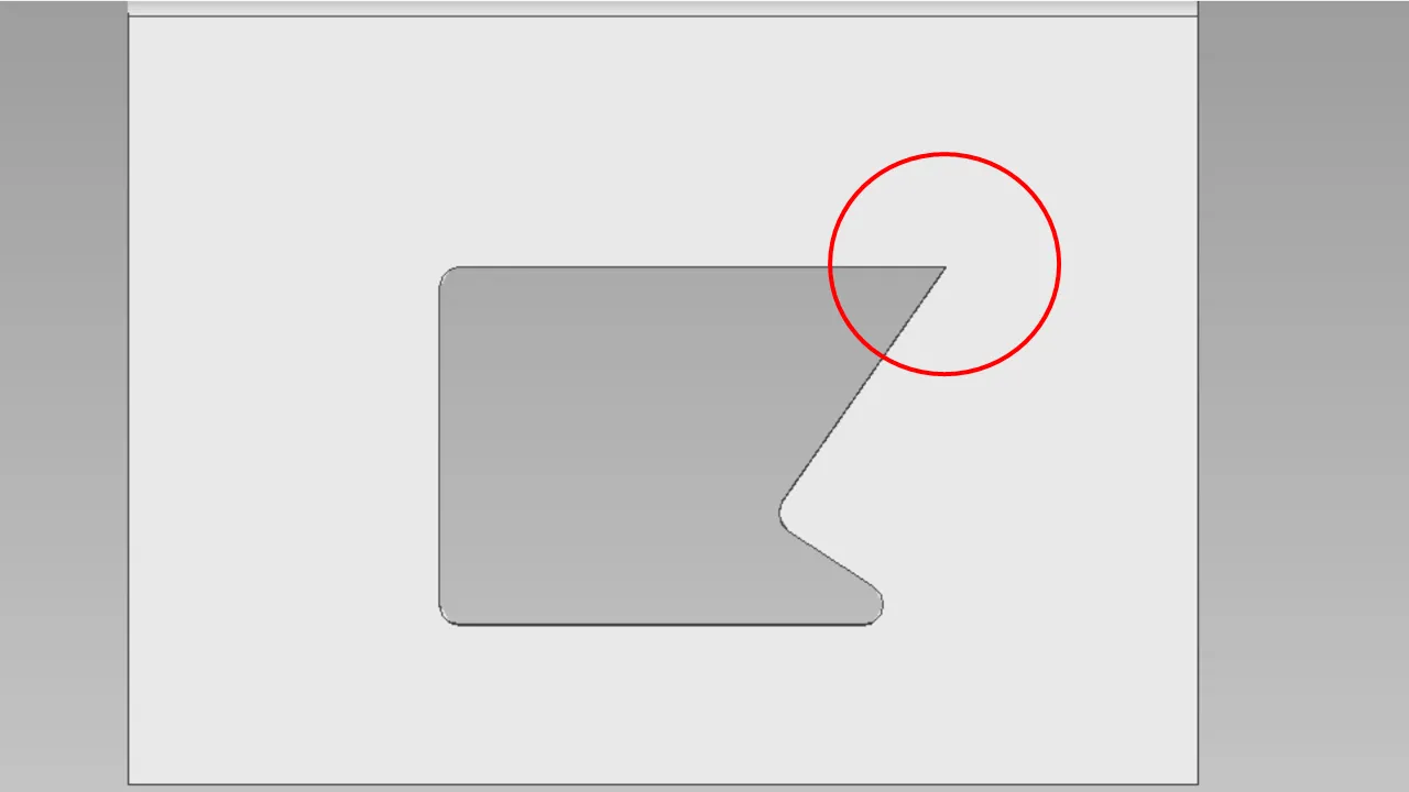
- Hole diameter: a hole that is too small relative to the material thickness will break the punch
- Slots: if the width is too narrow, or the length too short, they are equally unfeasible
- Corners of punched profiles: if a corner is sharp or acute, a turret punch press cannot produce it and the part moves to laser cutting
- Notches: notches that are too small damage the tooling
What is characteristic of holes is that the outcome is not only “cannot be made” but also “moves to a different process“. If the process changes, the cost and the lead time change with it. A quotation can differ from expectations for a reason that turns out to be a corner radius.
Will it stay undistorted?
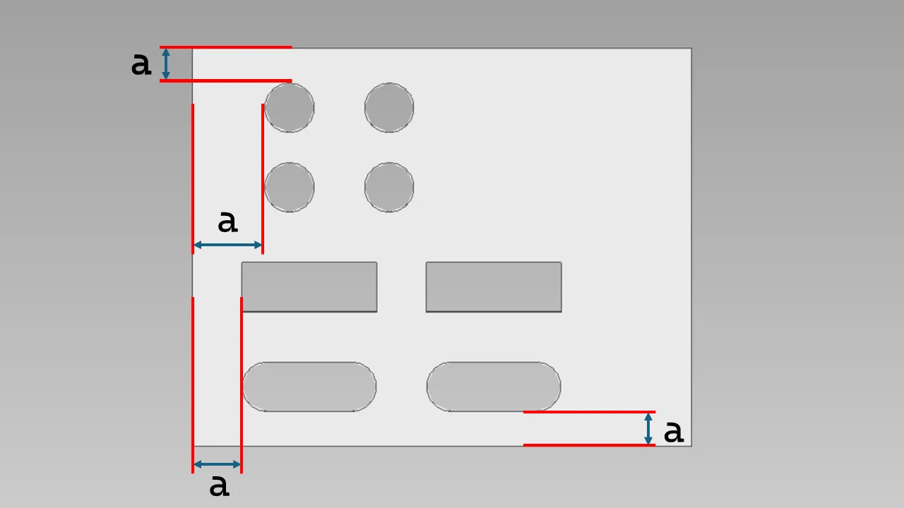
If a hole is close to an edge, or holes are close to each other, the material gives way during shearing and the hole distorts, or the web between two holes tears. This applies not only to round holes but equally to slots and square holes.
Holes near a bend line, and relief holes
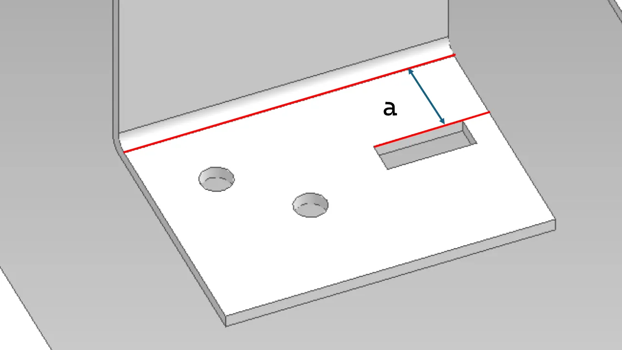
Because the material flows during bending, a hole close to the bend line is pulled and becomes elliptical. It is one of the classic causes behind the comment “we made it exactly as drawn, but the dimensions are out” in sheet metal.
Conversely, if a hole is deliberately placed so that it includes the bend line, it functions as a relief hole and suppresses distortion in the surrounding holes. In that case the usual rule for “distance from the bend line to a hole” does not apply as written.
In other words, having a hole near the bend line is not in itself a defect; the judgement changes depending on whether it is designed as a relief hole. This is a point where both human review and automated judgement easily go wrong, because design intent cannot be read from the shape alone.
- When placing a hole, are you looking at how that sheet will later be bent?
- Can it be told from the drawing or the model whether a hole near a bend line is a hole to avoid or an intended relief hole?
Tapped holes
Tapped holes come with tighter constraints than ordinary holes.
- Is there enough depth relative to the material thickness for the thread to hold (too shallow and the strength is not there)?
- Conversely, is it so deep that there is a risk of breaking the tap?
- Are tapped holes too close to each other, or too close to an edge?
Related items worth checking at the same time
Sheet metal parts are often not complete on their own, and when welding is involved a further set of constraints applies.
- Are the materials the same grade? Welding dissimilar materials becomes more difficult because of differences in melting point and the formation of intermetallic compounds
- Is the material suited to welding? Depending on thermal conductivity and the nature of the oxide film, some materials are hard to weld
- Is the weld line too long? A long continuous weld creates thermal distortion and the part warps
- Are there holes or tapped holes near the weld? If they overlap the bead, strength drops or tools for later operations interfere
- Is there space for the torch? Make sure the design does not leave the electrode or torch unable to reach once assembled
The details of welding (throat thickness, groove angle, spot pitch and so on) are largely left to the 2D drawing and the fabricator’s judgement rather than the 3D model. Managing what should be checked on the 3D model separately from what should be conveyed by drawings and instructions reduces gaps in the review.
Putting a checklist into operation
Creating a checklist is not the hard part. The hard part is keeping it running without letting it become a formality.
What to decide first is not the numbers, but where you measure from
Take the earlier example of a hole near a bend line. Whether you measure from the bend tangent line, from the start of the bend radius, or from the inner flat area, the value differs for the same shape. “Bend height” is the same: interpretations diverge depending on whether it is measured from the bend line or from the inner flat area.
When you develop an in-house standard, the discussion stalls on this definition of the datum before it ever gets to the values themselves. Put the other way round: once the datum is agreed, the values can be filled in by asking the fabricator.
- Add a figure to each item showing “from where, to where” the measurement is taken
- State explicitly, item by item, whether the bend radius is included in the distance
A list of numbers alone, without this, produces different judgements from different people and ends up unused. That is also why every item in this article comes with a figure.
Assume that values change from fabricator to fabricator
Fixing a single value makes it excessively strict for one fabricator and too loose for another. Structuring it so that the items are shared and the values are parameters per fabricator keeps the standard from breaking down as your supplier base grows.
Visual checking has its limits
Sheet metal alone reaches several dozen check items. Having people visually check every item on every part is not realistic. In practice, the more experienced the designer, the more they decide “this one is fine” and skip ahead. And what is skipped is what gets missed.
Anything whose judgement can be written in terms of shape and numbers can be judged automatically from the 3D model. Judgements that cannot be read from shape alone, such as design intent or functional requirements, remain with people. The relief hole above sits exactly on that boundary. This structure is common to the automation of design work in general.
What to automate and what people should review — we cover that division of labour in detail in What Is AI Drawing Inspection? How Manufacturers Automate Design Verification to Reduce Errors and Checking Hours.
The basic check items for sheet metal are listed in the resource below. Use it to take stock of what your own checklist should contain.
Frequently asked questions about sheet metal design checklists
How many check items should we have?
We would suggest not making the count a target. Start by taking stock of the cases where rework actually occurred in your own company, and build the items from there; that produces a list people use on the floor. Adopting a generic list as-is mixes in items that are unnecessary for your fabricators, and that is the entry point to it becoming a formality.
What should we refer to for specific thresholds?
Asking the fabricator is the most reliable route. Values change with equipment, tooling and material. The fabrication-limit guidelines published by parts procurement services and the like are useful as a rough guide, but note that those values assume that service’s own equipment.
Can’t we verify this with 3D CAD functions alone?
3D CAD with a sheet metal mode can detect some issues, such as shape interference and inconsistent thickness. However, judging “can this fabricator make it?” is beyond the scope of the standard functions. A separate mechanism is needed to bring in the rules of each fabricator.
When is the most effective time to run the check?
Rather than after the detailed design is fixed, it is effective to run it once at the point where the basic shape is decided. Bend sequence and the position of relief depend on the basic shape of the part, so fixing them later ripples out to the related parts as well.
If we introduce automated design verification, will human checking become unnecessary?
No. Rules that can be written in terms of shape and numbers can be automated, but design intent and functional requirements cannot be covered by automated judgement alone. You need to design the division of roles: what is automated and what people review.
Summary
A sheet metal design checklist is the constraints of the forming equipment translated into the designer’s language. For bends, “will it sit in the machine?”; for holes, “can it be punched, and will it stay undistorted?” Hold on to these two viewpoints and the individual items can be derived from the reasons behind them. Relief is not a separate topic; it appears within each of them, at the root of a bend and at holes on the bend line.
And specific thresholds change from fabricator to fabricator. That is exactly why what should be decided first when standardising in-house is not the values, but the definition of the datum — where you measure from.
Once the items reach several dozen, a model in which people visually check every one of them hits its limit. Shift the judgements that can be written in shape and numbers towards automation, and let people spend their time on the judgements that cannot be read from shape alone. The quality of sheet metal design is determined by how you design that division of labour.
The full list of 33 basic check items for sheet metal, milling and turning, including those covered in this article, is available in the resource below.
If you would like to discuss standardising design rules for your own fabricators, or checking them automatically from 3D models, you are also welcome to contact us.
This article was written by WOGO Inc., a University of Tokyo-originated startup developing systems for design verification, automated drawing inspection and design/drafting automation in manufacturing using 3D, CAD and AI technologies.