



2D Drawings
3D CAD
Generative AI
September 23, 2026
Can AI Build CAD Models? What Text to CAD and Drawing-to-3D Can and Cannot Do
 Updated on 2026/09/23
Index
Tell an AI what you want in words and a 3D model comes out. The technology called Text to CAD has become familiar over the past few years, and abroad there are commercial services that build a 3D model from a single sentence, and open projects that teach AI agents the procedure for generating CAD. So can AI really build CAD models that are usable in manufacturing?
What the shop floor wants to know is “and how correct is it?” We started testing early, using publicly available Text to CAD mechanisms both to build parts from written instructions and to read 2D drawings and raise 3D models from them. On the basis of that testing, this article sets out what today’s AI can and cannot do, and what it takes to use it well.
To give the conclusion first: simple parts with every dimension given can already be built correctly. Complex drawings still fall short on accuracy, and building exactly what was instructed does not mean the result can be manufactured. But that is less a limit of the AI’s ability than a matter of how the know-how people hold is taught to it, and where a person makes the judgement. And where rigour and repeatability are required, documents written in words are not enough.
Key points of this article
- For a simple part with every dimension written out, AI builds exactly what was instructed. Raising a 3D model from a drawing also matches the drawing, once the reading and verification procedure is in place
- Feed it a 2D drawing as one kind of input and, on complex drawings, what the drawing does not say remains: shapes without dimensions, what a note refers to, contradictions within the drawing itself. The AI alone cannot settle those
- “Correct” has two directions: (1) is it as instructed? and (2) can it be made, and does it meet the requirements? Give only the requirements for a sheet metal part and you get something that satisfies (1) but leaves no room for the bending tool
- The condition for using it well is that people put their own work into words. With the same AI, the result changes substantially before and after the know-how is conveyed. Where rigour and repeatability are required — analysing 3D geometry and design verification — you need a machine that measures to the same definition every time, not words
What is Text to CAD? Is the AI “drawing” the shape?
Text to CAD is the technology of generating a 3D CAD model from text. Abroad there are commercial services such as Zoo, which promises an editable 3D model from a single prompt, and in open source there are skill sets such as earthtojake/text-to-cad that teach AI agents the procedure for generating CAD. The generative AI features of the major CAD vendors are part of the same current, which we have organised in CAD AI Feature Comparison.
The name says “from text”, but what happens inside is a little different. At the centre of Text to CAD is an AI that handles language, like ChatGPT. That AI cannot draw shapes directly. Whether the input is text, an image or a drawing, it first rewrites what it received into a written specification, and then writes the procedure that builds the shape from that specification. What actually builds the shape is the CAD geometry engine.
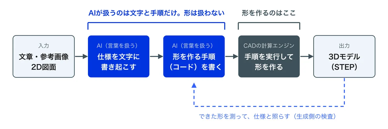
In that sense Text to CAD is less “a feature for instructing in text” than the technology of AI handling CAD itself. Whether the input is text or a drawing is only a difference at the entrance; inside, the same thing happens.
How correctly can AI build a CAD model?
First, note that “correct” runs in two directions.
(1) Is it as instructed? Did the AI read the specification conveyed in words or drawings correctly, and is the shape exactly that?
(2) Can it be made, and does it meet the requirements? Will the shape as instructed run on the machine, bend, clear interference, meet your own design standards? If something built exactly to the drawing cannot be manufactured, the drawing itself is the problem — and that has to be found too.
Inputs vary: text, images, drawings. Here we line up our test results using two of them — specifying dimensions in words, and having it read a 2D drawing. The first three look at (1); the last looks at (2).
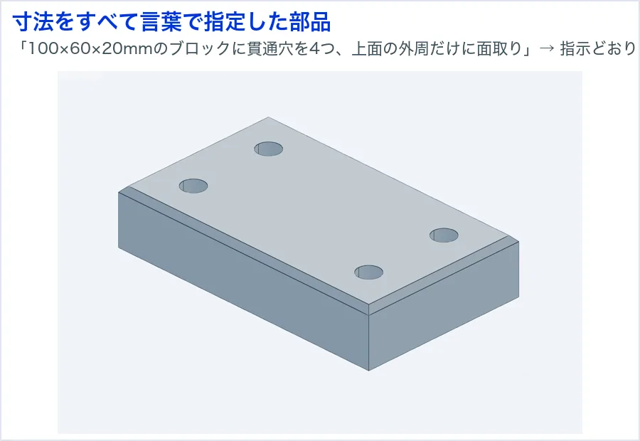
A part with every dimension specified in words: (1) built correctly
When every condition is stated — “a 100 x 60 x 20 mm block with four through holes, chamfered only around the perimeter of the top face” — no inference is required. Dimensions, hole positions and the extent of the chamfer all came out exactly as instructed.
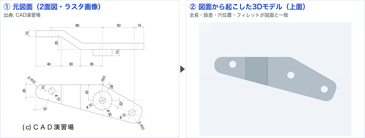
A simple drawing: (1) built as drawn
An example raised from an image of a hand-drawn-style two-view drawing. The drawing used was CAD Enshujo’s practice drawing “CAD exercise drawing f4-1”. Overall length, step, hole positions and fillets all came out as drawn.
A complex drawing: (1) as-is, mismatches remain
We ran one drawing from a public dataset through the same flow. The first model generated looked plausible at a glance, but overlaying the 3D on the original drawing to visualise the errors left clear mismatches.
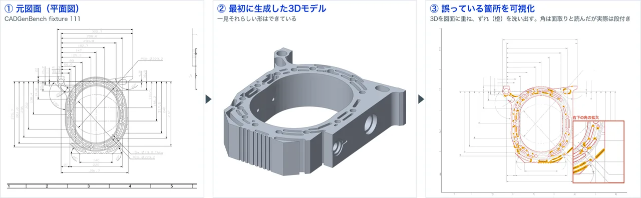
Most of the instructions that carried dimensions were right, but the places that went wrong were the ones tied to what the drawing does not say — shapes without dimensions, and contradictions in the drawing itself.
Those three are all about (1), as-instructed. Whether the remaining errors can be improved is dealt with in a later section. Last, we look at (2).
A sheet metal part from requirements only: (1) satisfied, (2) not manufacturable
Finally we gave the same AI only the requirements and had it build a sheet metal part: “a cable bracket with a channel section, made by bending 2 mm steel sheet. Mounting holes in the base, holes for cable ties low on both side walls, and the top edges folded inward so they do not cut the hand.” Nothing was said about manufacturability.
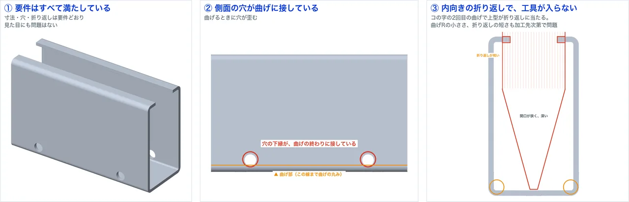
The model met every requirement — dimensions, hole positions, folds. It passes on (1). But the shape cannot be made in sheet metal.
- The side holes touch the bend. A certain distance is needed between the bend line and a hole; too close and the hole distorts when bent
- With inward folds, the bending tool cannot get in. On the second bend of the channel the upper punch has to pass between the two folds and reach the bottom, and at this opening and depth it collides
- The bend radius is small relative to the thickness, and the fold is short. Depending on the supplier’s material and tooling, it may not be viable
Are the errors a limit of the AI’s ability?
We do not think so. Break down what was wrong in the testing and the reasons fall into three kinds.
The first is a matter of method. It read by eye, it did not fix the scale, it took a note as authoritative and inferred the shape, the check after completion was visual. These are not a matter of intelligence but of procedure — and simply changing the procedure had the same AI produce a model that matched the drawing.
The second is the judgement that fills in what the drawing does not say. How to interpret a shape with no dimension; which of two contradictory dimensions to take. This is not reading accuracy but the judgement of someone who knows what the part is and how it is machined.
The third is that the criteria for manufacturability were never handed over. In the sheet metal example there was no statement of what to observe and what to prioritise when in doubt, so only the dimensional requirements were observed.
In other words, what is hard is not the AI, but that the know-how people hold — procedure, judgement, criteria — is not yet in a form that can be handed to it.
What does it take to use AI well?
In a phrase: people putting their own work into words.
AI is often compared to a highly capable person. But however capable, no one can work if you hand them only the CAD and the drawing and say “over to you.” What is this part, and how is it machined? Which part of the drawing is authoritative, and what takes priority when in doubt? Against what do you check the shape that comes out? When the tacit premises people hold are put into words and handed over, the AI’s results change.
An example: teaching the floor’s workflow as a tip
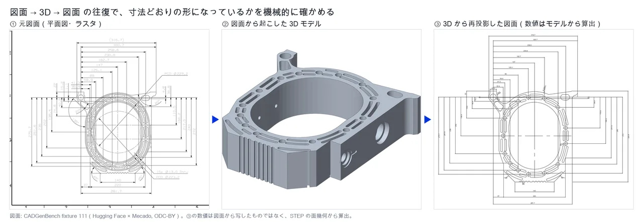
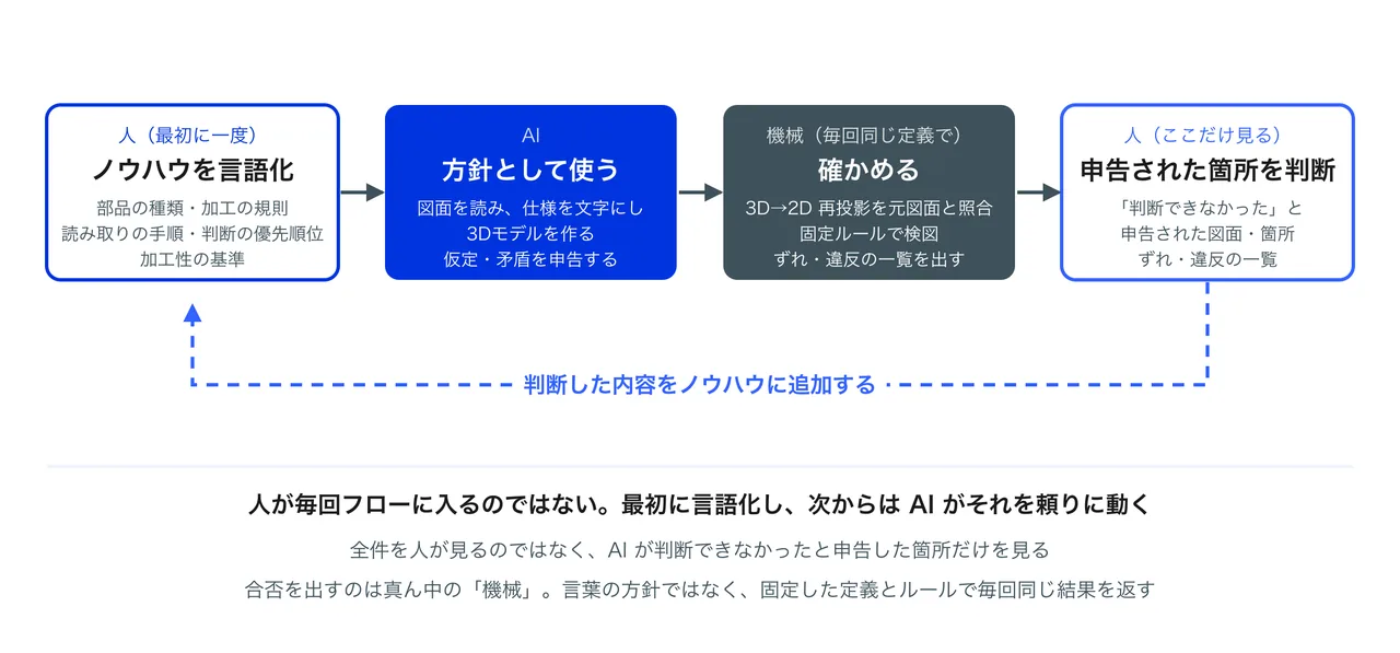
On a floor that raises 3D models from 2D order drawings, there is a routine for confirming that the model was raised correctly: drop the finished 3D back into a 2D drawing and match its dimensions against the original. It is a tip people acquired from experience. We taught that to the AI as it stands, because the AI’s self-check only looks at “does it match my own specification” — exactly what was missing.
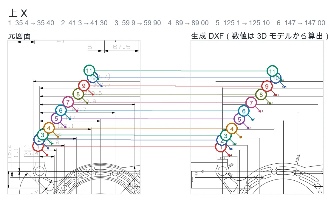
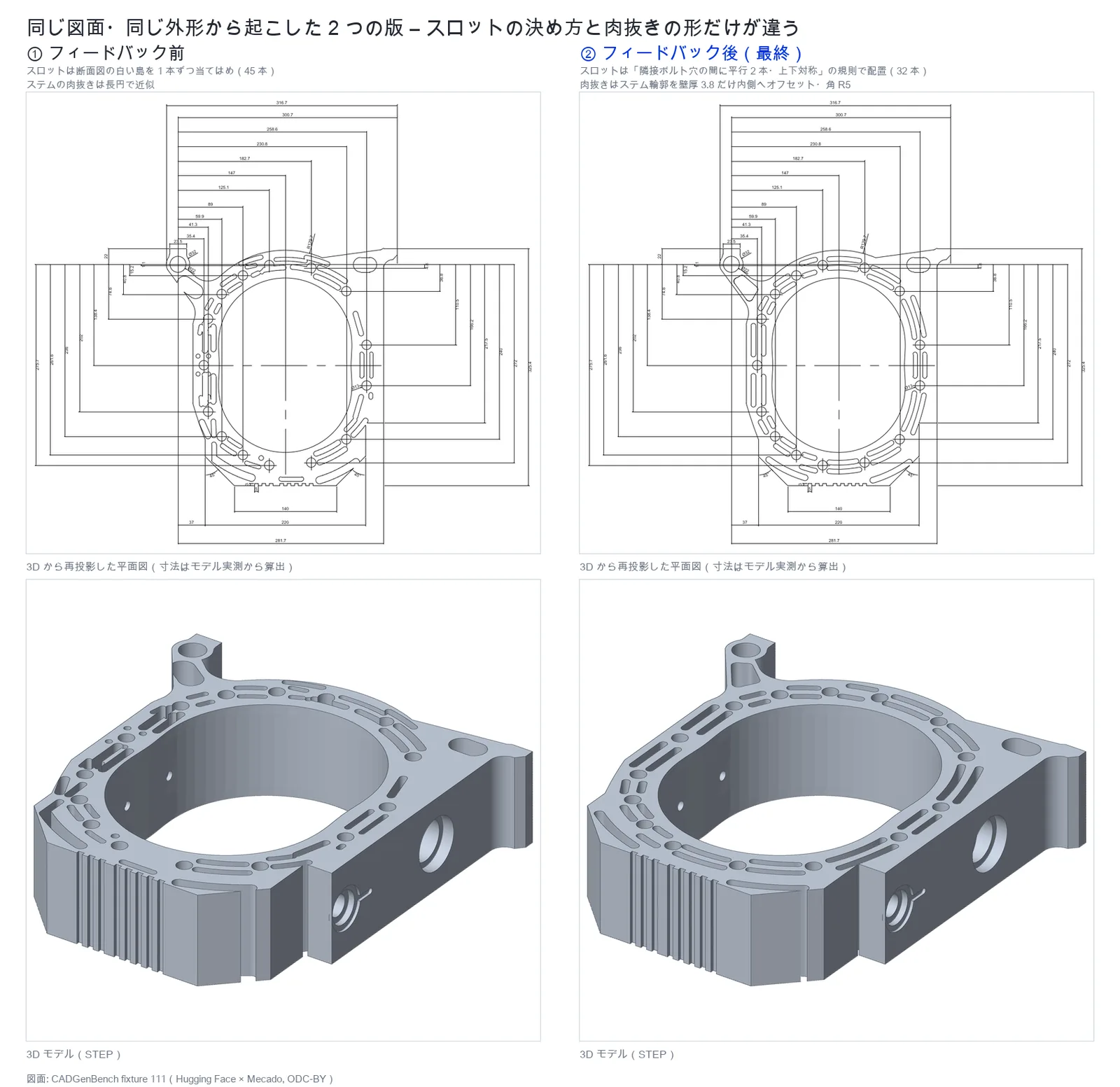
The left and right of Fig. 7 were raised from the same AI and the same drawing; the only difference is the know-how a person conveyed. In the first result (left) the slots were unevenly arranged and the shape of the lug pocket differed from the drawing. Once we taught the procedure — re-project the 3D into a drawing, match dimensions and shapes, correct what is off — and ran it again, it came out even, as on the right. The AI’s intelligence did not change. Know-how and tips are decisive for AI too.
Put the manufacturability criteria into words the same way (design verification)
Even when (1) is satisfied, (2) remains. Is there a radius at the bend? Is a hole too close to an edge or a bend line? Is the thickness constant? Can the tool reach? It is the step of applying the criteria set by the supplier’s equipment to the finished model. The problem in the sheet metal example could at least have been flagged as “the requirements and the criteria conflict”, had the criteria been in words. The check items for sheet metal are in our Sheet Metal Design Checklist, and the thinking on automation is in What Is AI Drawing Inspection?
This does not mean a person is in the loop every time
None of this means people check every case. It means people put the know-how into words at the start: the reading procedure, the machining rules per type of part, the criteria for judgement. Once that is clear, the AI works from it thereafter, and people only need to look at the drawings the AI flagged as “could not judge”. In fact, the reading criteria we built up by trial and error turned out to overlap almost entirely with the “how to read a drawing” rules in the open project we saw later. Know-how put into words can be shared, and it accumulates.
If you teach it in words, can everything be left to AI?
The answer in the previous section was that putting know-how into words and handing it over changes the AI’s results. So if you also teach it the manufacturability criteria in words, can design verification be left to it too? This is where there is a line that words alone do not cross.
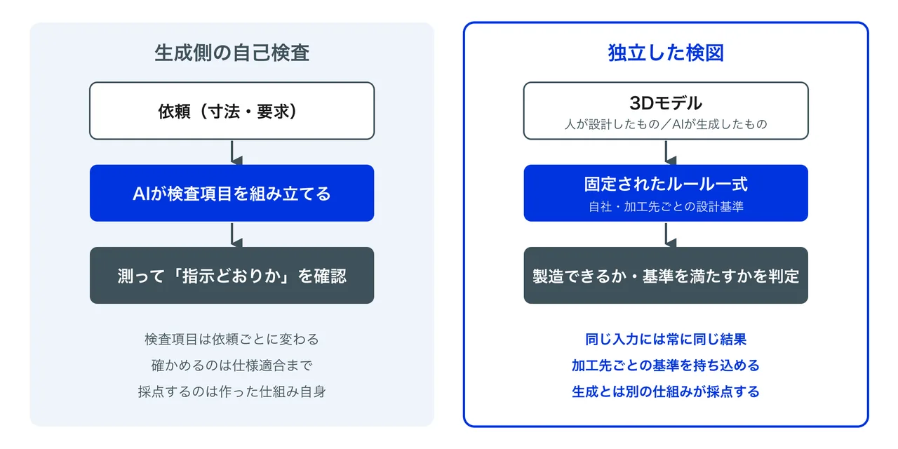
Know-how handed over in words is interpreted by the AI as it uses it. That suits things you want used flexibly according to the situation, such as tips and priorities of judgement. But a pass/fail judgement is a different matter. Ask in one line “can this sheet metal part be bent?” and the AI’s interpretation and method of measurement will not be constant. Is the distance from the bend line to the hole measured from the tangent of the bend, or from the centreline? The manufacturability review function of the open project mentioned above likewise warns that you must state where you measure from before comparing distances, and states that it is a procedure-based review and not a manufacturing certification engine. Because the AI also chooses the check items per request, there is no guarantee that running the same part twice runs the same checks.
The same goes for the self-check on the generation side. What it looks at is (1), and moreover “does it match the specification the AI itself wrote” — not agreement with the original instruction, and not (2), manufacturability. That is why, in the sheet metal example, a model that met the requirements came out as a shape the tool cannot enter.
So policy can be handed over in words. But there are places where pass/fail must not be decided in words: the parts that demand rigour and repeatability — analysis that measures 3D geometry to the same definition every time, and design verification that judges against the criteria of each supplier as fixed rules. That belongs not in a document written in words but in a machine mechanism independent of the generation.
| Handed over in words (policy) | Fixed in the machine | |
|---|---|---|
| Content | Type of part, machining rules, reading procedure, priorities of judgement | Definitions of how geometry is measured, judgement rules, criteria per supplier |
| Who decides | People | People decide; the machine holds it |
| What is asked of it | Judgement according to the situation | The same result for the same input, always |
| Who marks it | A person makes the final call | A mechanism separate from the generation |
Where should a manufacturer start when trying AI-based CAD generation?
- Decide the input. Rather than having it explain everything from text, start from inputs where the figures are already in place, such as work that raises 3D models from existing 2D drawings
- Have people decide the type of part and the machining rules first, and hand them over. Sheet metal or machined, how repeated features are arranged — these are the judgements that the reading depends on
- Receive the specification it read, plus a list of assumptions and contradictions, as deliverables. Do not accept only the 3D model
- Teach the floor’s checking procedure as a tip. Put in the step of re-projecting a drawing from the 3D and comparing it with the original, and make the list of discrepancies what people review
- Put it through design verification independent of the generation. Models the AI built go through the same criteria as models people built
- Start with simple parts, and accumulate know-how in words. Write down what people judged as policy, and the AI can use it from the next run
In this order, the checking mechanism stays the same whether the AI gets better or worse. It is the idea of building the part that does not depend on the AI’s performance first. For how automation of design work is likely to progress, see How Generative AI Changes Design Work: A Timeline of Mechanical Design AI.
Frequently asked questions about Text to CAD
Can you not have it build a part from text alone?
For a simple part whose dimensions can all be specified in words, yes, and the shape comes out as instructed. But for real production parts, writing the shape and the requirements exhaustively in words is harder than drawing the drawing. Having it read an existing 2D drawing is one of the strongest ways to use it.
How accurately can AI build a CAD model?
With fully dimensioned input it builds exactly what was instructed. From a drawing it depends on the procedure: reading by eye misread major dimensions, whereas measuring to read and then overlaying on the drawing to check produced a match. What the drawing does not say — shapes without dimensions, what a note refers to, contradictions in the drawing — needs human judgement.
Can a model built by AI go straight to manufacturing?
Not as it is. You have to confirm separately that it is as instructed (1) and that it can be made and meets the design standards (2). The sheet metal part built from requirements alone satisfied (1) while leaving no room for the bending tool. Point (2) is confirmed by design verification independent of the generation.
If AI reads the drawings, does the job of raising 3D models disappear?
The work shifts from “raising the model” to “putting judgements into words” and “checking what was flagged”. Judgements such as the type of part, the machining rules and how to handle contradictions stay with people, but once put into words the AI can use them from the next run.
If we teach design verification in words too, can it be left to AI?
Policy can be handed over in words, but pass/fail should not be decided in words. A one-line “can it be bent?” does not make the interpretation or the method of measurement constant; you need the definition of how to measure and the judgement rules fixed, in a mechanism that returns the same result for the same input.
Summary
AI can build CAD models, by handling language to write the CAD operating procedure. Simple parts with full dimensions can already be built correctly, and raising a 3D model from a drawing also matches what the drawing instructs, once the procedure of measuring to read and checking by re-projection is in place. But building what was instructed and being able to manufacture it are different things: the sheet metal part built from requirements alone left no room for the bending tool.
What remains on complex drawings is the judgement that fills in what the drawing does not say. What is the part and how is it machined? Which of two contradictory dimensions applies? That is not a limit of the AI’s ability but a consequence of human know-how not yet being in a form that can be handed to it. With the same AI, results changed substantially before and after the know-how was conveyed. The condition for using it well is that people put their own work into words. Once that is done and the AI flags only what it could not judge, people do not have to review every case.
There are, however, places where pass/fail must not be decided in words: analysis that measures 3D geometry to the same definition every time, and design verification that judges manufacturability against fixed rules. That has to be held as a machine mechanism independent of the generation, not as a document written in words.
If you are interested in a mechanism that verifies models generated by AI and models designed by people against the same criteria, you are welcome to request our materials or contact us.
This article was written by WOGO Inc., a University of Tokyo-originated startup developing systems for design verification, automated drawing inspection and design/drafting automation in manufacturing using 3D, CAD and AI technologies.