



3D CAD
Rework
Manufacturing DX
September 21, 2026
Resin Part Design Checklist: Wall Thickness, Draft Angle and Undercut Rules to Check
 Updated on 2026/09/21
Index
Rework on resin parts surfaces only once the mould has been built. “You will get a sink mark here.” “This shape will not release from the mould.” “It warps, so the dimensions do not hold.” Every one of them could have been caught at the design stage.
Design checking for a resin part means confirming, before the drawing is released, that the shape you have designed will release from the mould, that the molten resin will flow into every corner, and that it will settle into the intended shape and dimensions as it cools and shrinks. This article organises the points to check into two: whether the part releases from the mould, and what happens as it cools and shrinks.
As in the sheet metal and machining articles, the emphasis here is not on specific threshold values but on what to check and why. Resin thresholds change with the grade of resin, the moulding conditions and the structure of the mould. Grasping the reasoning that fixes a value is more useful than memorising the value, because the reasoning also applies to shapes you are seeing for the first time.
Key points of this article
- Unlike the sheet metal question of whether the material survives being deformed, or the machining question of whether the tool can reach, resin design rules are a restatement of whether the part releases from the mould, and what happens as it cools and shrinks
- There are two things to look at. Whether it releases from the mould is decided by draft angles and undercuts; what happens as it cools and shrinks is decided by wall thickness
- The single most frequent subject of discussion in resin is wall thickness. Thinner walls cut material cost; thicker walls give strength. But thick sections cause sink marks and warpage, which makes wall thickness the one dimension where strength, cost and quality collide at the same time
- Specific thresholds change with the grade of resin and the structure of the mould. The first thing to settle when building an in-house standard is not a value but where the mould splits and in which direction the part is drawn
What does designing a resin part actually decide?
Designing a resin part means deciding the shape, the wall thickness, the grade of resin and the direction in which the part is drawn from the mould, on the premise of injection moulding, where molten resin is poured into a mould and solidified. Where sheet metal deforms a single sheet and machining removes material, in resin the shape of the mould becomes the shape of the product directly.
Broadly, a designer decides the following four things in resin design.
- Grade of resin: ABS, PP (polypropylene), PC (polycarbonate), POM, nylon and so on. On top of strength, heat resistance, chemical resistance and cost, how easily it flows (flowability) and how it shrinks (shrinkage rate) govern whether a shape is feasible
- Wall thickness: the thickness of the basic wall of the product. Strength, material cost, cycle time, sink marks and warpage all converge here
- Mould split and draw direction: where the mould is split and in which direction the part is drawn. Until this is settled, neither draft angles nor undercuts can be judged
- Gate and ejector positions: where the resin is injected from and where the solidified part is pushed out. This includes deciding whether the flow marks and ejector marks will appear on a cosmetic surface
The difference from sheet metal and machining is release from the mould
The sheet metal design checklist was organised around bends and holes, and the machining design checklist around tool diameter and tool length. In both, the centre of the constraint was the physics of the moment: either the material or the tool.
In resin, the centre of the constraint moves to the movement of the mould. A mould only opens in a fixed direction. If a wall is perpendicular to that direction, the part clings to the mould and will not release; if there is a feature that crosses the draw direction, a mechanism that slides the mould in from the side becomes necessary. The question is not whether the shape is good or bad, but whether that shape is compatible with the movement of the mould.
Resin changes shape as it cools and shrinks
There is one more constraint that sheet metal and machining do not have. Resin enters the mould molten and shrinks as it cools and solidifies. How much it shrinks is set by the grade of resin, and the design dimensions are built into the mould with that shrinkage allowed for.
The problem is that if it does not shrink uniformly, the shape distorts. Thick sections cool more slowly, shrink later and leave a dip in the surface. That is a sink mark. If parts of the piece cool differently, stress remains inside and the part warps after it leaves the mould. Where sheet metal and machining follow the rule that the shape is fixed once processing is finished, resin keeps changing shape even after it leaves the mould. That is the essence of what makes resin design difficult.
Why checking resin parts leads directly to rework
Compared with sheet metal and machining, rework in resin has a distinct character: it surfaces late and it costs more to go back.
With sheet metal or machining, the supplier looks at the drawing and comes back with “we cannot make this.” Resin is different. Even if the shape has a problem, the mould can still be built, and sink marks, warpage and release failures only appear once resin is actually injected. In other words, you find out after the mould is finished.
And a mould is an order of magnitude more expensive than the part itself, and takes time to build. Fixing the shape means fixing the mould, and if the change cannot be reworked, the mould has to be built again. The weight of a single design change is not comparable with sheet metal or machining.
There is also a structural problem: product design and mould design sit with different people, often at different companies. What we often hear when talking with design departments in manufacturing is that the product design side designs to its own in-house technical standards, while the fine adjustments needed to make the part mouldable are left to the judgement of the mould design side. As a result, know-how does not travel between design and the mould, and the mould trial (test shot) is repeated again and again.
Checking resin, then, is the work of finding the shapes that will trouble the mould side before the mould is built. We have set out the cost structure of rework in the cost of rework in manufacturing design and the issues in 3D/2D design verification.
The resin design rules to check first
Below are the representative items in which the two axes, whether the part releases from the mould and what happens as it cools and shrinks, appear most directly.
Is there a draft angle?
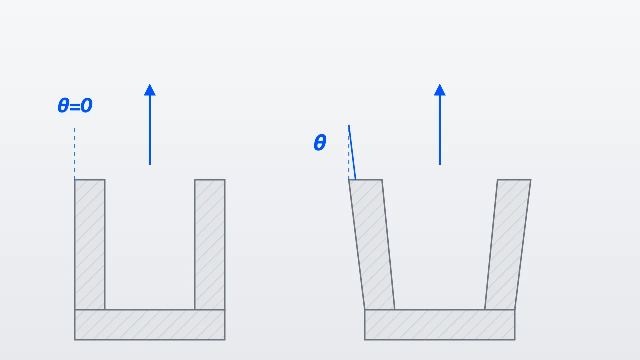
When the part is drawn out of the mould, a wall that is exactly perpendicular to the draw direction rubs against the mould face over its entire area. It either will not release, or it releases with scuff marks or stress whitening. A slight slope is therefore given to the wall. That is the draft angle.
The angle required changes with the grade of resin, the height of the wall and the surface finish (whether there is a texture, and how deep it is). In particular, a textured surface needs a larger draft the deeper the texture is. Specifying a deep texture for the sake of appearance and ending up with too little draft is a common misunderstanding between the two sides.
- Does every wall have a slope relative to the draw direction?
- Do ribs, bosses and internal lattice features also have draft? (These are easy to miss because they are not visible from outside)
- Is the draft on a textured face sufficient for the depth of that texture?
Is the wall thickness uniform, and neither too thin nor too thick?
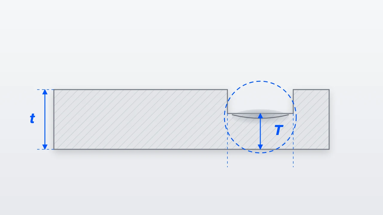
Wall thickness is at the centre of resin design. Thinner walls lower material cost and cycle time, but the resin may not reach every corner, giving short shots, and strength drops as well. Thicker walls give strength, but they cool more slowly and cause sink marks, where the surface dips, and voids, where a cavity forms inside.
What matters is not thickness in itself but thickness that differs from place to place. Where thin and thick sections are mixed, they cool at different times and shrink by different amounts, and the part warps. The rule of thumb is to level the thickness at the minimum that delivers the strength required, and to reinforce locally with ribs where extra strength is needed.
Wall thickness is the subject that comes up most often in design discussions about resin parts. Because material consumption translates directly into cost in resin parts, there is very strong demand to see at the design stage how thin it is possible to go. Go too thin, on the other hand, and you get short shots and insufficient strength. Think of wall thickness as the one dimension where strength, cost and quality collide at the same time.
- Is the basic wall thickness roughly level across the whole part?
- Do the places where thickness changes transition gradually rather than as a step?
- Can material relief (coring out the unnecessary material) be added to thick sections?
- Does any thin section form a dead end partway along the path the resin flows down?
Is the root of the rib too thick?
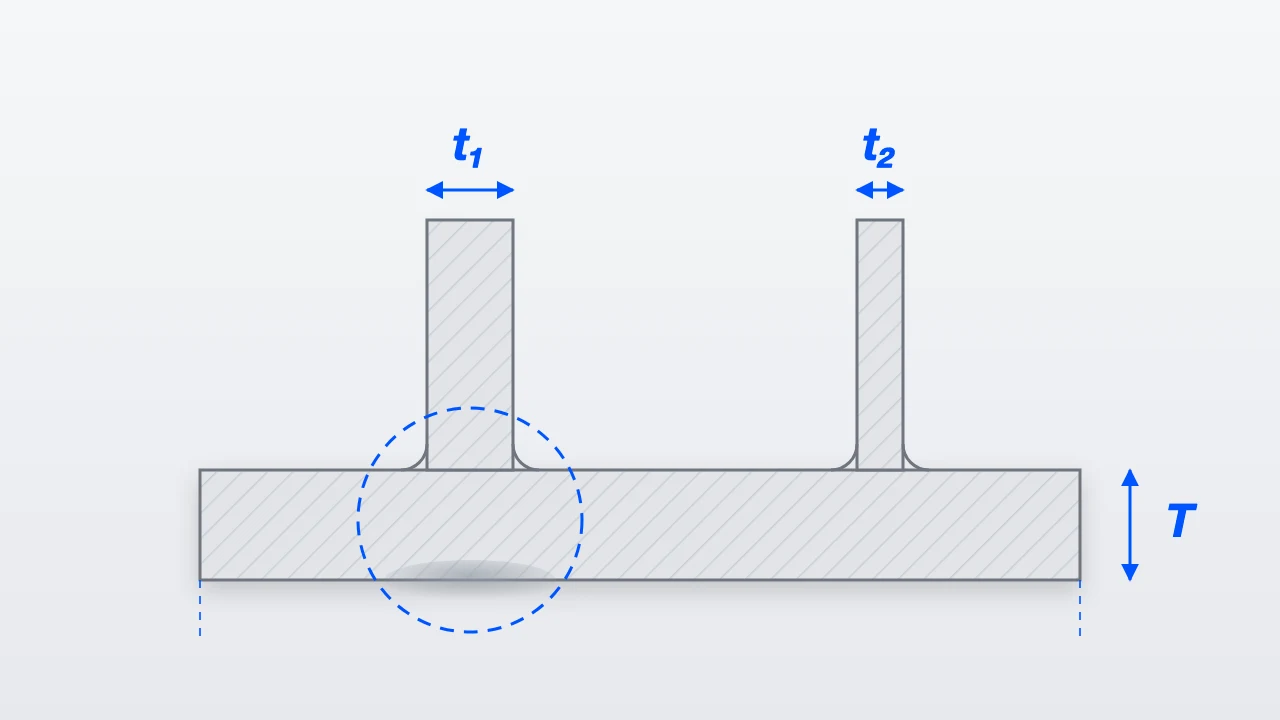
A rib is a feature for gaining strength without increasing wall thickness. If the rib is made the same thickness as the wall, however, resin pools at the root where the rib meets the wall and creates a locally thick section. Because that section cools late, a sink mark appears on the surface behind the rib. It is a failure that occurs easily when a rib is raised behind a cosmetic surface.
Ribs are therefore made thinner than the nominal wall thickness. As for the radius at the root, a larger radius reduces stress concentration, but by that much more material pools there and sink marks become more likely. The judgement of whether to favour strength or freedom from sink marks enters here.
- Is the rib thickness held down relative to the nominal wall thickness?
- Is the radius at the root of the rib reasonable as a balance between sink marks and strength?
- Is the reverse face of the rib a cosmetic surface? If it is, are sink marks acceptable there?
- Does the rib itself have a draft angle?
Is material pooling at the root of the boss?
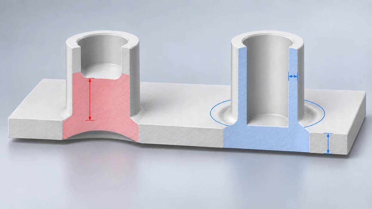
A boss is a cylindrical feature for receiving a screw or an insert. As with a rib, material pools at the root where it rises from the wall and a sink mark appears on the reverse face. Because a boss is thicker than the wall, the symptom shows up more readily than with a rib.
The countermeasures are to core out the material at the root of the boss (material relief), and to move the boss slightly away from the wall and connect it with a rib. Both come from the same idea: keep the strength required while avoiding a locally thick section.
- Has material relief been cored out at the root of the boss?
- Is the wall of the boss not excessively thick relative to the nominal wall thickness?
- Is the reverse face of the boss a cosmetic surface?
- Do both the inner and outer diameters of the boss have a draft angle?
Is there an undercut?
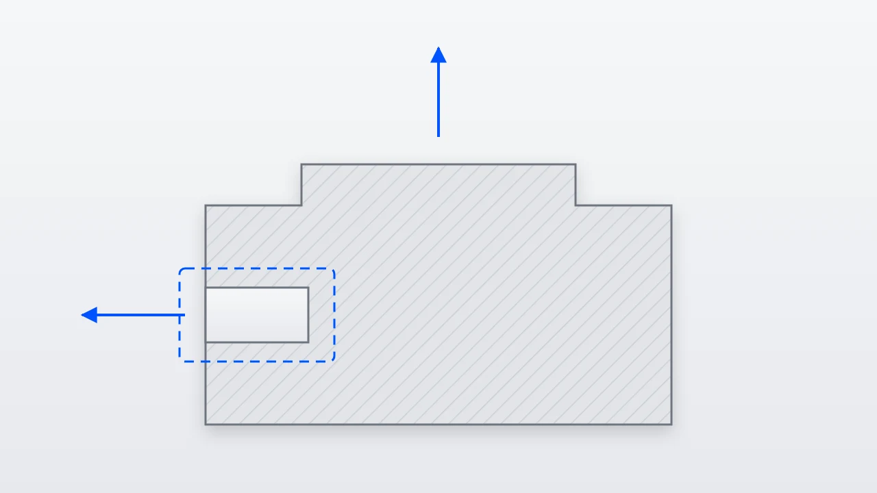
A shape that catches against the direction in which the mould opens is called an undercut. Holes in a side face, tabs projecting outwards and threads cut on an inner face all qualify.
A part with an undercut can still be made. It is enough to build a mechanism into the mould, such as a slide that moves in from the side or an angled pin that escapes diagonally. But by that much, the structure of the mould becomes more complex, cost and lead time rise, and there are more things that can fail. The structure described in the machining article, that it is not impossible to make but it becomes expensive, appears on the mould side in resin.
Checking for undercuts is therefore not a question of whether one exists, but of whether that function is worth the extra complexity in the mould. You judge it against alternatives such as changing the draw direction, splitting the shape, or dividing the part into two and assembling them.
- Is there any shape that catches against the draw direction of the mould?
- If there is, can it be handled with a mechanism such as a slide? Is there space on the mould side for that mechanism?
- Can that shape be avoided by changing the draw direction or by dividing the part?
- With the slide fully travelled, is the necessary area and strength still secured?
There are other considerations beyond these
These five items are the ones in which the two axes, whether the part releases from the mould and what happens as it cools and shrinks, appear most clearly. In real design there are many more considerations: the position and number of gates (the inlets for the resin), weld lines where flows of resin meet, the parting line left where the mould is split, ejector pin marks, and warpage caused by how the part is cooled.
What all of them have in common is that they cannot be judged from the shape of the product alone, and have to be considered together with the structure of the mould.
Related items worth checking as well
A resin part is not complete on its own; it is assembled, and its shape changes while it is in use.
- Snap-fit design: does the deflection and stress in the tab stay within what that resin allows? Where the part is repeatedly attached and detached, fatigue also has to be considered
- Stress at inserts and press-fits: where a metal part is embedded or pressed in, stress is applied to the resin continuously. Has creep, the deformation that occurs over time, been taken into account?
- Specifying cosmetic surfaces: does the drawing state clearly which faces are visible? The tolerance for gate marks, weld lines, ejector pin marks and sink marks changes depending on whether the face is cosmetic
- How tolerances are set: because the dimensions of resin also change with moulding conditions, tightening tolerances with the same instincts as for a metal part does not work. Have they been narrowed to the places that matter for fastening and fitting only?
- The effect of a material change: change the resin and both the shrinkage rate and the flowability change. The premises on which the shape was feasible collapse, so a material change calls for a full review of the shape
These cannot be judged from the geometry of the 3D model alone, and much of it is left to the instructions on the drawing and to agreement with the mould maker. Managing what you check on the 3D model separately from what you convey through the drawing and its notes reduces the number of checks that get missed.
Putting the checklist into practice
As written in the sheet metal and machining articles, building a checklist is not the difficult part. The difficulty is keeping it turning without letting it become a formality. In resin, the discussion stalls at one further point.
What to settle first is not a value but the mould split
Most resin rules are defined relative to the draw direction of the mould. A draft angle is an angle relative to the draw direction, and an undercut is a question of whether the shape catches against the draw direction. In other words, unless where the mould splits and in which direction the part is drawn have been settled, none of the rules can be judged.
In sheet metal the discussion stalls on where to measure from, and in machining on which tools and equipment are assumed. In resin it stalls on the mould split and the draw direction. Put the other way round, settle that first and the remaining values can be filled in by checking with the grade of resin and the mould maker.
- Settle the position of the mould split and the draw direction early in design, even provisionally
- Leave that decision inside the 3D model (give it a datum plane or a coordinate system that shows the draw direction)
- State explicitly in the checklist that if the mould split changes, the judgements change too
Align the language between product design and mould design
The biggest reason rework repeats in resin is not the shape itself but the fact that know-how does not flow between product design and mould design. Product design designs to technical standards, and the adjustments that make the part mouldable are left to the mould side. As a result, the same failure recurs on a different part.
To prevent this, do not make the checklist a tool for the product design side alone. Take the comments that come back from the mould maker in as items, and share them with the reason why each comment was raised. Once that loop starts turning, the list changes from something people are made to follow into something that prevents the next failure.
There is a limit to visual checking
Automated checking of resin is a clearly harder area than sheet metal or machining. The reason is not accuracy but the fact that where to measure cannot be settled.
Sheet metal is a bent sheet, so both the sheet thickness and the bend height have obvious places to measure. Machining, too, is based on a block or a bar. Resin parts, however, have many free-form surfaces, radii that change from place to place and faces that are not flat. When you say “the wall thickness here”, it is not self-evident along which normal it should be measured. We have in fact been told by designers working on automotive resin exterior parts that identifying the location to measure is itself difficult.
On top of that, resin parts involve many judgements about appearance and styling. “Is this surface beautiful?” and “is this split line inconspicuous?” cannot be written as inequalities the way manufacturability can. Judgements that can be written in shapes and numbers can be automated, but this area stays with people.
We set out how to divide what is automated from what people look at in more detail in what is AI drawing inspection? How manufacturers automate design verification to cut design errors and inspection hours.
Note that what WOGO’s automated design verification service currently covers is sheet metal, machining and assemblies, and that for resin parts we are working on extending coverage. If you are interested in verification for resin parts, please get in touch with us individually.
Frequently asked questions about the resin part design checklist
How thin can the wall thickness go?
It is decided by the grade of resin and the distance the resin has to flow. The more easily a resin flows the thinner it can go, and the longer the flow distance the more thickness is needed. For specific values, confirming with the moulder is the reliable route. Going thinner lowers material cost and cycle time but raises the risk of short shots and insufficient strength, so the safe order is to fix the lower limit from the strength required first, and then confirm that it can be moulded.
How many degrees of draft should I give?
It changes with the grade of resin, the height of the wall and the surface finish. A textured face in particular needs a larger draft the deeper the texture, so decide the appearance specification and the draft together. Mould makers hold guideline figures of the form “this draft for this texture on this face”, so confirming once the appearance specification is decided is the reliable route.
Can sink marks be eliminated completely?
In theory they can be reduced by removing differences in thickness, but a real part has to have thick sections for strength and function. In practice the design becomes one of collecting sink marks where they do not matter. The order is: do not raise ribs or bosses behind a cosmetic surface; if one is unavoidable, hold the thickness down with material relief; and if a sink mark still remains, state the cosmetic surfaces on the drawing and agree the tolerance for sink marks.
If we have moulding analysis (CAE) in 3D CAD, is a checklist unnecessary?
They have different roles. Moulding analysis simulates what happens if you inject with this shape. It is strong for verification that includes mould conditions, but preparing and running the analysis takes time. A checklist picks up the things that should be cleared away before an analysis is run at all. Items such as a missing draft angle or the thickness of a rib can be judged during design without waiting for an analysis.
Can resin be covered by automated design verification as well?
If a rule can be written in shapes and numbers, it can in principle be covered. Resin does, however, have many free-form surfaces, and the definition of where to measure wall thickness or draft is not as self-evident as in sheet metal or machining, which makes it a harder area than those two. At WOGO too, resin parts are an area where we are working on extending coverage, and we are taking enquiries individually.
Summary
A resin part design checklist is a translation of the movement of the mould, and of how resin cools and shrinks, into the language of the designer. Whether it releases from the mould is decided by draft angles and undercuts; what happens as it cools and shrinks is decided by wall thickness. Hold on to these two viewpoints and the individual items can be derived from their reasons.
Unlike sheet metal and machining, problems in resin surface after the mould has been built. That is exactly why checking before the drawing is released translates directly into mould cost.
And specific thresholds change with the grade of resin and the structure of the mould. What should be settled first when standardising in-house is not a value but where the mould splits and in which direction the part is drawn. Until that is settled, none of the items can be judged.
Resin is an area where rules that can be written in shapes and numbers mix with judgements that cannot, such as appearance and styling. Push the judgements that can be written towards automation, and let people spend their time on the ones that cannot. Design quality for resin parts, too, is decided by how you design that division of labour.
For sheet metal and machining (milling and turning), we publish a free list of basic check items organised on the same thinking. It does not include resin items, but the way it is organised, listing an item name together with what it prevents, can be used as a template when you build your own checklist for resin.
If you would like to discuss standardising design rules for resin parts, or checking them automatically from 3D models, you are welcome to contact us.
This article was written by WOGO Inc., a University of Tokyo-originated startup developing systems for design verification, automated drawing inspection and design/drafting automation in manufacturing using 3D, CAD and AI technologies.