



3D CAD
Rework
Manufacturing DX
September 21, 2026
Assembly Design Checklist: Interference, Assemblability and Tool Clearance Items to Verify
 Updated on 2026/09/21
Index
Even if every individual part can be made exactly as drawn, that does not mean the product can be assembled. “This hole does not line up with that one.” “The tool will not fit.” “The tolerances stacked up and the last plate will not go in.” The comments that come back from the assembly floor are not found by checking parts one at a time.
An assembly design check means confirming, before release, whether the relationships between parts hold, and whether the process of assembling them holds. This article organises what to check into two groups: “does the shape as it stands hold?” and “does the process of building it up and taking it apart hold?”
What decisively separates this from a single-part checklist is that time enters the picture. Nothing may interfere in the finished state, and yet part way through the build a part needs a path to travel along, and a tightening tool needs space to sit in. That this “intermediate state” appears neither on the drawing nor in the 3D model is what makes assembly checking hard.
Key points of this article
- Where single-part verification asks “can this part be made?”, assembly verification asks “do the relationships between parts hold?” They look at different things, so passing every part individually still leaves the assembly problems
- The check splits into two layers. Whether the current shape holds (interference, clearance, hole positions, tolerance stack-up) and whether the build process holds (insertion paths, tool clearance, assembly sequence, service space)
- Bolt holes and tapped holes that do not match the mating part are the classic case of parts that are correct on their own but do not work in combination, and it only comes to light once every part has arrived
- The essence of the difficulty is that a shape can hold statically and stop holding once time is introduced. And the assembly sequence does not exist as information inside the 3D model
Assembly design checking: what is actually being looked at
An assembly design check takes the state in which several parts are combined and confirms whether the relationships between those parts hold. Where verification of a single part is complete within that one part, assembly verification looks at the space between one part and another.
The ideal order has two stages. First, for each part, confirm that the part can be made. Once that passes, confirm at the assembly or unit level that the combination really does hold. The first stage is the ground covered by the checklists for sheet metal, machining and plastic parts. This article covers the second.
The difference from single-part verification is that it looks at relationships
What single-part verification looks at is the relationship between the shape of that part and the means of production — the machine or the mould. The information needed for the judgement is closed within that part.
In an assembly, the judgement needs information from several parts at the same time. Does this hole line up with that one? Can this gap be held once tolerances are taken into account? When this part goes in, does another part get in the way? Looking at one part alone does not produce an answer.
Static soundness and the soundness of the build process
Assembly checking divides further into two.
- Static soundness: in the finished state, are parts cutting into one another, is the necessary gap there, do the hole positions line up? These can be judged directly on the 3D model
- Soundness of the build process: on the way to that state, is there a path for the part to travel, does the fastening tool fit, can it be built in that order? This is information that does not appear in the finished-state model
The second of these is what makes assembly checking hard. Even shown a model that is perfectly assembled as a shape, “how is that bolt supposed to go in?” cannot be answered by looking at the model.
Why assembly checks lead directly to rework
Rework on assemblies has two characteristics that single parts do not.
One is that it surfaces late. The problem appears when every part has arrived and assembly begins. By that point machining of every part is finished, and both the budget and the lead time have been spent. A defect in a single part stops before machining; a defect in an assembly does not.
The other is that it propagates. If hole positions do not line up, fixing one of the two parts may not be enough. Move the position of the mating part and the parts beyond it are affected as well. A single mismatch spreads into remaking and re-ordering several parts.
The cost structure of rework is set out in The “cost of rework” in manufacturing design, and the issues around 3D and 2D verification.
Items that confirm whether the shape as it stands holds
First, the items that can be judged on the finished-state 3D model.
Do parts interfere with one another?
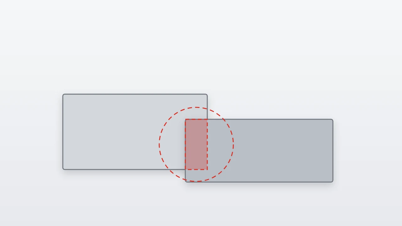
This is the most basic check. If parts occupy the same space, they cannot be assembled as they are. Most 3D CAD systems have interference checking as a standard function, so this item itself is relatively easy to confirm.
What causes problems in practice is omissions and records. An interference check produces no result unless it is run, and depending on the CAD system no record of having run it remains. If you cannot keep a record of who checked what configuration and when, you lose track of whether it was re-checked after each design change.
- Has the interference check been run on every unit?
- Is there a record of the configuration that was run and the result?
- After a design change, was it re-run over the affected range?
- Have deliberate overlaps (press fits, deformation from fastening) been organised as exclusions?
Is the necessary clearance held?
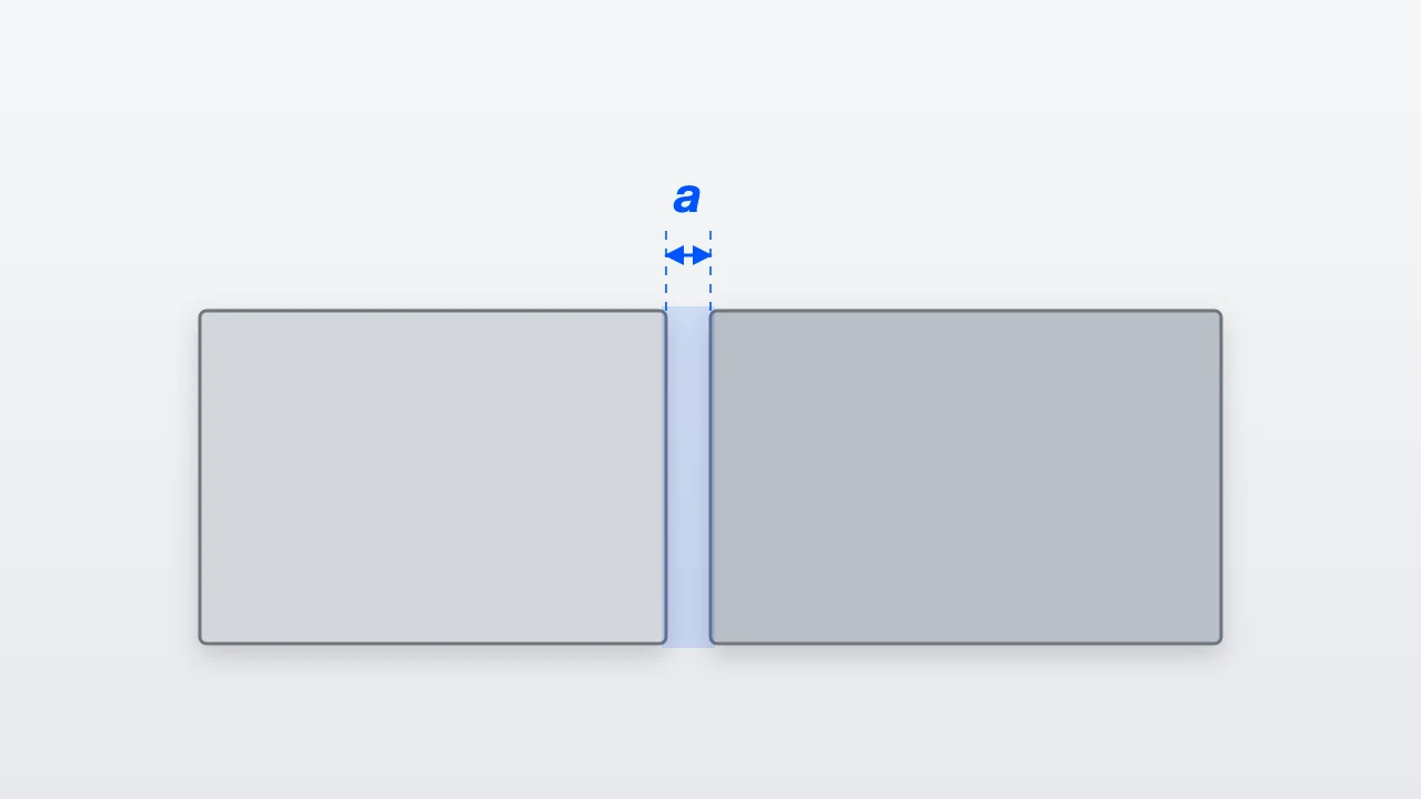
Not interfering and having the necessary gap are different things. Parts touching with zero gap do not interfere on the model, but in the physical product they make contact through tolerances, thermal expansion, deflection under load and vibration.
How large the gap needs to be changes with what the gap is for. A simple assembly allowance, the travel of a moving part, heat dissipation around a hot component, routing for wiring and piping. The criteria differ by purpose, so a single uniform value cannot decide it.
- Does the moving part avoid interference with other parts across its whole range of travel?
- Is there the necessary space around components that generate heat?
- Are the routes for wiring and piping, and their bend radii, held?
- Does a gap remain once tolerances and thermal deformation are taken into account?
Do hole positions and sizes match the mating part?
Holes for fastening only take on meaning once they span two or more parts. Looking at one part drawing alone does not tell you whether they match.
Misalignment almost always comes from changing the design of only one of the parts. The hole pitch was changed, the plate thickness was changed and the position moved, the part was mirrored. In every case the changed part is internally consistent, but its relationship with the mating part has broken.
- Do the hole positions and pitches agree between the parts being fastened?
- Does the hole diameter correspond to the size of the bolt or screw being used?
- Is the combination of clearance hole and tapped hole correct (are both tapped by mistake)?
- Do the slotted holes for position adjustment provide the range of adjustment required?
Does tolerance stack-up make it impossible to assemble?
When several parts are arranged in series, their dimensional tolerances stack up. The phenomenon is that every individual part is within tolerance and yet the combination will not go together.
The awkward part is that every part is a “pass”. Nothing is rejected at inspection. And still it will not go in at the last step of assembly. In that case a decision on the design side is needed: bias the tolerance of one of the parts to one side, or provide an adjustment allowance.
- Have the chains of dimensions involved in assembly been identified?
- When tolerances are stacked along that chain, does the necessary gap remain?
- Is there an adjustment allowance, or an adjustment mechanism, that absorbs the stack-up?
- Are the places where tolerance should be biased to one side indicated on the drawing?
Items that confirm whether the build process holds
Next, the items that do not appear in the finished-state model.
Is there a path to get the part in?
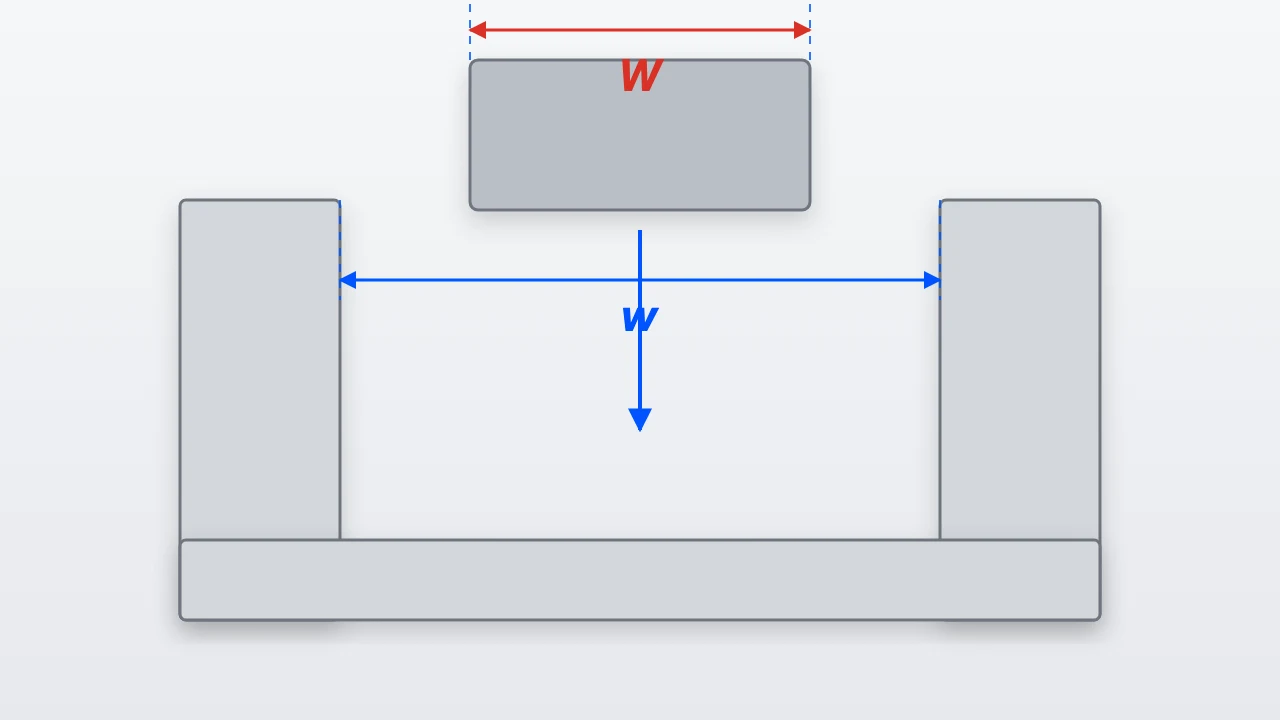
A part sitting in its final assembled position and the part being able to travel there are two different things. To put a part into a space enclosed on all sides, you need both the dimensions of the entrance and a path through it.
Where the part has to be rotated as it goes in, or tilted to pass through, you have to confirm that nothing interferes across the whole of that motion. A finished-state interference check cannot make that confirmation.
- Is there a path that carries the part to its final position?
- Can the part pass the narrowest point on that path?
- Where tilting or turning is required, is there no interference across the whole motion?
- Is there space along the path for the hands or the jig that hold the part?
Does the fastening tool fit?
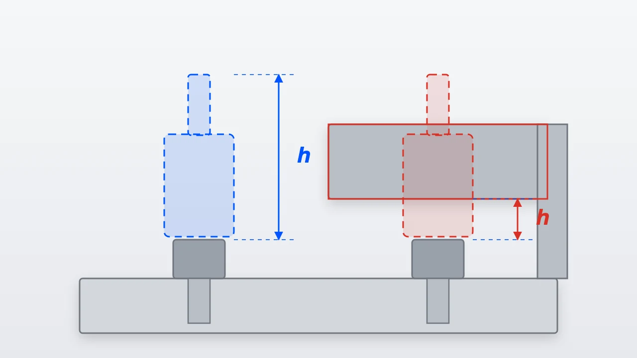
Tightening a bolt needs space above the bolt head for a wrench or a screwdriver, and further space to turn it in. A bolt sitting in place and a bolt that can be tightened are not the same thing.
The space required changes with the type of tool. A socket wrench needs height above the head, a spanner needs an angle to swing through sideways, a powered screwdriver needs length for the body to sit in. Unless which tool is assumed has been settled, the space required is not settled either.
- Is the space for the tool held at the fastening point?
- Has the type of tool assumed (socket, spanner, hex key, power tool) been settled?
- Is the angle, or the swing, needed to turn the tool held?
- Where a hand has to get in, is there space for the hand?
Does the assembly sequence hold?
Problems of tool clearance and insertion path mostly come back to the assembly sequence. Fit this part first and the bolt on the next part cannot be tightened. Build it up as units and then join them, and there is no problem. The same shape holds or does not hold depending on the order.
And the assembly sequence, while it exists as the designer’s intent, is not in the 3D model as information. Unless the design side states it explicitly, the floor will assemble it according to the floor’s own judgement.
- Does the design side have an intended order in which this configuration is built?
- Is that order in a form that reaches the assembly floor?
- Is the unit of a sub-assembly (a unit built up in advance) clear?
- Does the order hold with the equipment on the floor (crane capacity, whether it can be turned over, working space)?
Can it be taken apart and serviced?
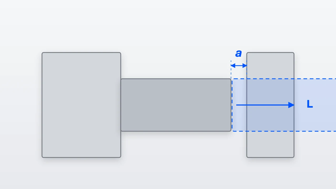
Even if it can be built, it cannot be serviced unless it can be taken apart. Parts that need replacing, and places that are inspected periodically, need space for removal.
The item most easily overlooked is withdrawal clearance. Parts drawn out along an axis — shafts, pins, filters, cartridges — need space equal to their own length. In the finished-state model that space exists as “somewhere with nothing in it”, so other parts tend to get put there.
- Do frequently replaced parts have a removal path and the space for it?
- Is the withdrawal clearance held for parts drawn out along an axis?
- Do the places that need inspection or adjustment have visual and tool access?
- Does the disassembly order hold as the reverse of the assembly order?
Putting the checklist into operation
What to decide first is not a value but “how much is treated as one block”
For sheet metal the starting point was “where do we measure from?”, for machining “which tools and equipment do we assume?”, for plastics “where do we split the mould?” For assemblies, what has to be decided is the unit of a sub-assembly.
Unless how much is treated as a pre-built unit is settled, judging tool clearance does not hold. Judge from the finished state alone that “there is no space above this bolt” and bolts that are in fact tightened at the unit stage are raised as problems too. Conversely, once the unit of a sub-assembly is settled, it is enough to look at whether fastening holds within that unit.
- Decide and record the unit of a sub-assembly at the design stage
- Reflect that unit in the structure of the 3D model (the assembly tree)
- Make the intended assembly order part of what design hands to the floor
Assembly know-how is not a matter of years of experience
There is one more fact that matters in operation. Whether someone can judge whether an assembly holds does not line up with their years of experience as a designer.
What we hear on site is a designer with twenty years of experience saying “let us ask him before we go ahead” about someone who has been in that department for about ten years. Judgement about assembly depends on experience specific to that department, that product and that equipment. Which means the knowledge is easily lost through transfers and retirements.
That is exactly why it is worth writing the content of each comment out as an item and keeping it. Keep “why this shape was a problem” with its reason attached and part of that experience can be handed on.
There is a limit to checking by eye
The number of items to check in an assembly grows further than for a single part. There are as many relationships as there are combinations of parts, and the combinations grow rapidly as the part count rises. Given that one machine is made up of hundreds to thousands of parts, having people confirm every relationship is not realistic.
What to automate and what people review — the thinking behind that division is set out in detail in What is AI drawing inspection? How manufacturing design verification is automated to cut design errors and verification hours.
Frequently asked questions about assembly design checklists
Is the interference check in 3D CAD not enough on its own?
It is effective for detecting static interference. However, not interfering and being assemblable are different things. Whether the necessary clearance is held, whether the tool fits, whether there is a path to get the part in, and whether it still holds once tolerances are stacked cannot be judged by a standard interference check. There is also the problem that many CAD systems leave no record of the check having been run, so you cannot trace whether it was confirmed after each design change.
How should tolerance stack-up be checked?
Start by identifying the paths along which the dimensions involved in assembly connect in series. Add up the tolerances along that path and see whether the necessary gap remains. The awkward part of this problem is that the individual parts can all be within tolerance and the stack-up still not hold. The response is either to issue an instruction biasing the tolerance to one side, or to provide an adjustment allowance or an adjustment mechanism.
Which tools should we assume when deciding tool clearance?
Base it on the tools actually used on your assembly floor. A socket wrench, a spanner, a hex key and a power tool each need a different envelope, and a power tool in particular needs room for the body of the tool. Unless the design decides “this joint is tightened with this tool”, the space required cannot be fixed. The reliable route is to agree a list of assumed tools with the assembly floor.
How should we decide the unit of sub-assembly?
Match the units that the assembly floor actually builds first. A unit that looks ideal from the design side will not be used if it does not work with the equipment on the floor: crane capacity, whether the part can be turned over, the working space. Reflect the sub-assembly units agreed with the floor in the structure of the 3D model, and check fastening and insertion paths unit by unit; that reduces gaps in the review.
Summary
An assembly design checklist is a translation, into the designer’s language, of whether the relationships between parts hold. There are two things to look at: whether the shape as it stands holds (interference, clearance, hole positions, tolerance stack-up) and whether the build process holds (insertion paths, tool clearance, assembly sequence, service space).
Passing every single-part check still leaves the assembly problems, because what is being looked at is different. And unlike single parts, a defect in an assembly surfaces once every part has arrived, and propagates into remaking several parts.
The dividing line in checking is whether time enters the picture. Items that can be judged on the completed model, and whether the assembly process holds, are different kinds of check. The latter only becomes judgeable once people have decided the unit of sub-assembly.
And judgement about assembly depends on experience specific to that site, not on years of experience. Writing comments out as items with their reasons attached is the only way to hand that knowledge on.
As for the basic items to check on the single-part side (sheet metal and machining), the list is published free of charge. It does not include the assembly items, but it is the first of the two stages in the idea of checking in two steps.
If you would like to discuss automating interference and assemblability checks on your assemblies, you are welcome to contact us.
This article was written by WOGO Inc., a University of Tokyo-originated startup developing systems for design verification, automated drawing inspection and design/drafting automation in manufacturing using 3D, CAD and AI technologies.